EN
BTR185 INSTALLATION AND USE MANUAL - REV009A
30
BTR1854 - Installation
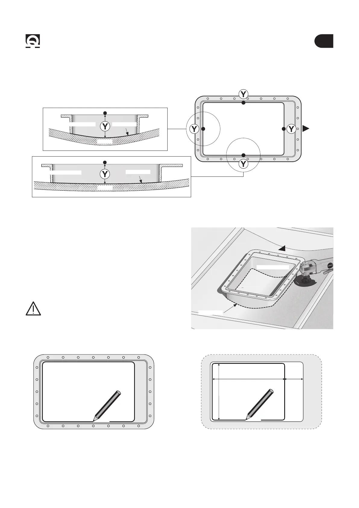
WARNING: keep into account the minimum dimen-
sions for the nal positioning of the hinge (see g. 12
to page 32).
Fig. 1C
HULL
• On the hull, Mark with a felt-tip pen the internal perimeter
of the counter ange (g. 2).
CUT LINE
• Lay the properly-cut counter ange and check that the four
sides t the hull, or adjust them until they do t in the posi-
tion where the counter ange is meant to be xed.
Fig. 2 Fig. 3
• Remove the counter ange and mark the cutting area:
350 x 280 mm (13" 25/32 x 11" 1/32) (g. 3).
350 mm 95 mm
280 mm
4.1 - Counter ange’s installation
BOW
BOW
HULL
COUNTER FLANGE
COUNTER FLANGE
CUT LINE
CUT LINE
COUNTER FLANGE
COUNTER FLANGE
• Shape the central section of the 4 sides of counter ange Y in order to adjust them to the hull curve (Fig. 1C).