22
GB
RETRACTABLE THRUSTER BTR185 - IT GB - REV004B
REF
X
Y
Z
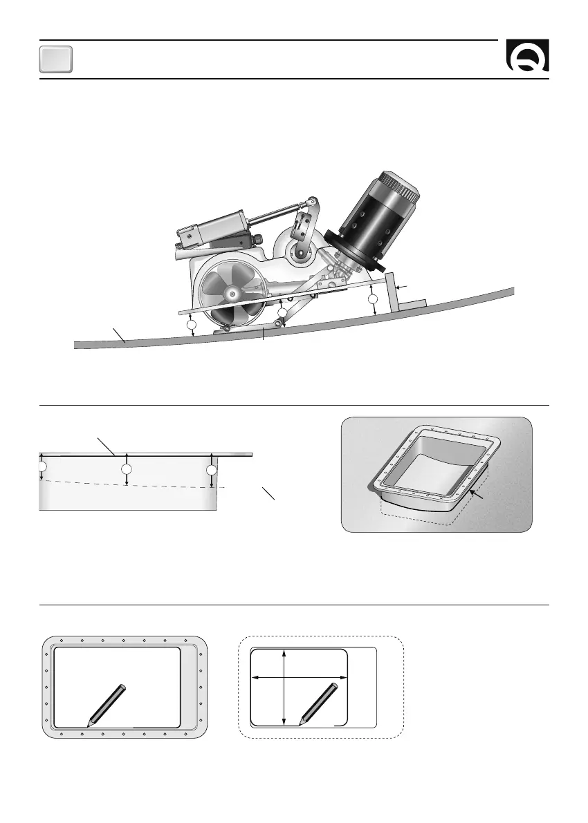
Installation positioning
Directly access inside the hull, where the thruster will be installed.
Record the heights (
X Y Z) detected on the larger side of the support.
Repeat the operation to also detect the heights of the shorter sides and adapt the support to the shape of the hull. Once
trimmed the support, temporarily lock in position marked (REF) to enable verifications of the final dimensions.
Fig. 1
CLOSED THRUSTER
HULL
METAL PLATE
Y
Z
Fig. 2
HULL
SUPPORT
Once the correct position is verified, mark the hull with the internal shape of the support (Fig. 3a).
Remove the support, measure and mark the hull opening using the dimensions in figure 3b.
The thruster position must enable easy maintenance operations.
F
280 mm
350 mm
Fig. 3a Fig. 3b
Position the thruster in stand-by position (closed) inside the hull, making it rest on the metal plate integral to the tun-
nel. Detect the heights (X Y Z) between the lower part of the flange and the hull. Realise references (REF) that, once the
thruster is removed, enable arranging the support in the same position.
INSTALLATION