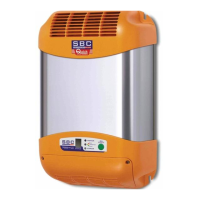
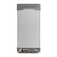
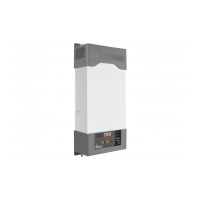
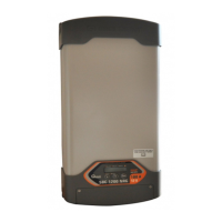
The Quick SBC NRG+ series is a range of high-quality battery chargers designed for nautical equipment, offering superior performance for marine applications. These chargers are available in both Mini Power (SBC 140 NRG+ FR) and Low Power (SBC 250 NRG+ FR, SBC 300 NRG+ FR, SBC 365 NRG+ FR, SBC 500 NRG+ FR) models, catering to various battery capacities and voltage requirements.
Function Description:
The SBC NRG+ battery chargers are designed to efficiently charge multiple groups of batteries using a three-stage IUoU charging characteristic. This intelligent charging process ensures optimal battery health and longevity. The chargers can differentiate charging for various battery types, including open or sealed liquid electrolyte, Gel, AGM, and Optima® batteries. They are equipped with integrated output fuses for enhanced safety and can supply full power even with low AC mains voltage. The devices are compatible with generators and offer comprehensive protection against short circuits, overloading, output overvoltage, and overheating. They are designed for fixed internal installations and can operate effectively across a wide range of ambient temperatures, featuring a variable speed cooling fan for optimal thermal management.
Important Technical Specifications:
Output Characteristics:
- Maximum Output Current:
- SBC 140 NRG+ FR: 12 A
- SBC 250 NRG+ FR: 25 A
- SBC 300 NRG+ FR: 30 A
- SBC 500 NRG+ FR: 40 A
- SBC 365 NRG+ FR: 15 A
- Charge ABSORPTION Voltage (12V models):
- EL open: 14.1 Vdc
- EL sealed / Gel / AGM: 14.4 Vdc
- Optima®: 14.7 Vdc
- Charge ABSORPTION Voltage (24V model - SBC 365 NRG+ FR):
- EL open: 28.2 Vdc
- EL sealed / Gel / AGM: 28.8 Vdc
- Optima®: 29.4 Vdc
- Charge FLOAT Voltage (12V models):
- EL open: 13.4 Vdc
- AGM: 13.6 Vdc
- EL sealed / Gel / Optima®: 13.8 Vdc
- Charge FLOAT Voltage (24V model - SBC 365 NRG+ FR):
- EL open: 26.8 Vdc
- AGM: 27.2 Vdc
- EL sealed / Gel / Optima®: 27.6 Vdc
- DC Absorption from the batteries: < 3.5 mA
- Residual Ripple: < 100 mV RMS
- Charging Characteristics: Automatic in three stages IUoU
- Number of Outputs: 2 (SBC 140 NRG+ FR, SBC 250 NRG+ FR) or 3 (SBC 300 NRG+ FR, SBC 500 NRG+ FR, SBC 365 NRG+ FR)
- Supply Voltage: 264 ÷ 83 Vac, with power reduction under 108 Vac
- Frequency: 45 ÷ 66 Hz
- Maximum Absorption (230/240 Vac):
- SBC 140 NRG+ FR: 0.9 A
- SBC 250 NRG+ FR: 1.8 A
- SBC 300 NRG+ FR: 2.2 A
- SBC 500 NRG+ FR: 2.7 A
- SBC 365 NRG+ FR: 2.0 A
- Maximum Absorption (120 Vac):
- SBC 140 NRG+ FR: 1.7 A
- SBC 250 NRG+ FR: 3.4 A
- SBC 300 NRG+ FR: 4.2 A
- SBC 500 NRG+ FR: 5.3 A
- SBC 365 NRG+ FR: 4.0 A
- Power Factor (cos φ): 1.00
- Efficiency: ≥ 83% to ≥ 87% depending on model
Protections:
- Reverse polarity (through fuse)
- Overload
- Output short circuit
- Overvoltage in output
- Overheating
Ambient Characteristics:
- Operating Temperature: -15 ÷ +70 °C, with linear power reduction over +45 °C
- Noise Level: < 43 dBA @ 1 m (SBC 140 NRG+ FR) and < 45 dBA @ 1 m (other models)
- Cooling: Variable fan speed
- Humidity: Max. 95% RV without condensation
Case:
- Material: Aluminium
- Dimensions (WxHxD):
- SBC 140 NRG+ FR: 114 x 187 x 71 mm
- SBC 250 NRG+ FR, SBC 300 NRG+ FR, SBC 365 NRG+ FR: 114 x 252 x 71 mm
- SBC 500 NRG+ FR: 114 x 275 x 71 mm
- Weight:
- SBC 140 NRG+ FR: 1.1 kg
- SBC 250 NRG+ FR, SBC 365 NRG+ FR: 1.6 kg
- SBC 300 NRG+ FR: 1.6 kg
- SBC 500 NRG+ FR: 1.8 kg
General:
- Safety Standard: EN 60335-2-29
- EMC Standard: EN 55022/B - FCC TITLE 47 PART 15 SUBPART B CLASS B
Usage Features:
- Installation: Installation must be carried out by qualified personnel. The charger should be installed in a dry and airy spot, as close to the batteries as possible, to ensure full power operation. It can be mounted on a horizontal surface or a vertical wall, with the output connector facing downwards. A minimum distance of 5 cm from walls or objects is required around the perimeter (excluding the support base). Vertical installation is recommended for better cooling.
- Battery Type Selection: The charger allows optimization of the charge process based on battery type (Open Liquid Electrolyte, Sealed Liquid Electrolyte, Gel, AGM, Optima®) via a rotary switch in the terminal board area. This selection should only be made when the charger is switched off.
- Charging Phases:
- BULK phase (constant current): The charger supplies maximum rated current (or a reduced value if power reduction factors are present) when batteries require more current than available, such as during start-up or when batteries are low.
- ABSORPTION phase (constant voltage): The charger maintains a constant ABSORPTION voltage, supplying the necessary current until the current required falls below the transition threshold between ABSORPTION and FLOAT.
- FLOAT phase (maintenance): The charger maintains a constant FLOAT voltage when the current required is less than the transition threshold. In this phase, batteries absorb increasingly low current, allowing them to remain on charge without risk of overload. The transition threshold is 20% of the maximum nominal output current.
- Control Panel: Features three LEDs (LED POWER, LED FLOAT, LED CHARGE) to indicate operational status and problems.
- Steady Light (2 LEDs on): Indicates FLOAT phase or CHARGE status (BULK or ABSORPTION phase).
- Slow Flash (2 LEDs on alternated with 1 LED on): Indicates output short circuit/overload, overtemperature (ambient temp > +70°C, output suspended until temp < +50°C), or high temperature (ambient temp > +50°C, current limited until temp < +50°C).
- Quick Flash (2 LEDs on alternated with 3 LEDs off): Indicates output overvoltage (internal malfunction, requires Quick® customer service).
- Quick Flash (2 LEDs on alternated with 1 LED on): Indicates No AC (FLOAT or ABSORPTION) where output power is suspended until mains voltage returns above 83 VAC.
- Connections: The equipment includes an AC power cord. An overvoltage category III switch must be installed for ON/OFF control. Connections to AC mains must comply with local electrical codes. Before connecting/disconnecting AC or DC wires, ensure the device is disconnected from AC mains by a bipolar switch and from batteries by a battery isolator. Positive battery terminals connect to positive charger terminals, and negative battery terminals connect to negative charger terminals. Unused positive output terminals must be kept free. The "MASTER" output should be used for the most frequently used battery group (typically the service group).
Maintenance Features:
- The battery charger does not require specific maintenance.
- To ensure optimum performance, it is recommended to check the cables and electrical connections once a year.