6
Pub. No. 2200772355 — October 2006
FIGURE 5 — INSTALLATION
CONNECTION TO THE COMPRESSED AIR
SYSTEM
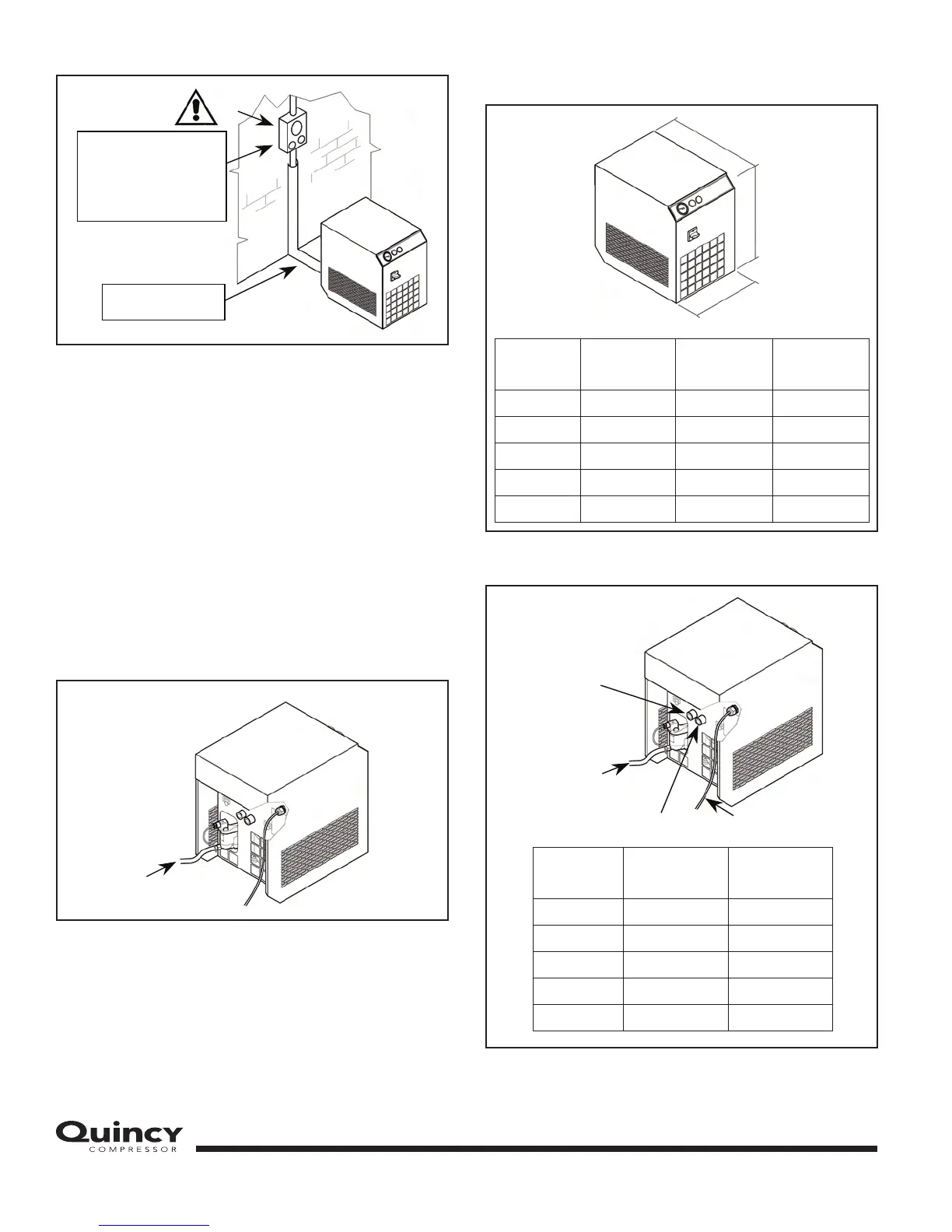
Fit a manual shut-off valve between the machine and the
compressed air system so that the dryer may be isolated
during maintenance operations. Drainage of condensate
(automatic) passes outside the machine through a flexible
tube (2 in Figure 6) that may be inspected. Drainage must
comply with local codes.
ALL DAMAGE DUE TO THE FAILURE TO COMPLY
WITH THESE INSTRUCTIONS CANNOT BE
ATTRIBUTED TO THE MANUFACTURER AND MAY
INVALIDATE THE GUARANTEE.
FIGURE 6 — CONDENSATE PIPE
DIMENSIONS AND TECHNICAL DATA
FIGURE 7 — DIMENSIONS
FIGURE 8 — CONNECTION
1
ATTENTION:
Dryer must be wired to the power
supply through a fused disconnect
switch or circuit breaker in
accordance with national and
local electrical codes.
Minimum 24 in (0.6 m)
on all sides.
2
Type
L
in (mm)
W
in (mm)
H
in (mm)
QPNC 10 13.78 (350) 20.09 (510) 19.05 (484)
QPNC 15 13.78 (350) 20.09 (510) 19.05 (484)
QPNC 25 13.78 (350) 20.09 (510) 19.05 (484)
QPNC 35 13.78 (350) 20.09 (510) 19.05 (484)
QPNC 50 13.78 (350) 20.09 (510) 19.05 (484)
H
W
L
Type
A
NPT
B
NPT
QPNC 10 1/2-14 Male 1/2-14 Male
QPNC 15 1/2-14 Male 1/2-14 Male
QPNC 25 1/2-14 Male 1/2-14 Male
QPNC 35 1/2-14 Male 1/2-14 Male
QPNC 50 1/2-14 Male 1/2-14 Male
(A) AIR INLET
CONDENSATE
DRAINING
(B) AIR OUTLET
ELECTRICAL CABLE
 Loading...