3 Back Panel
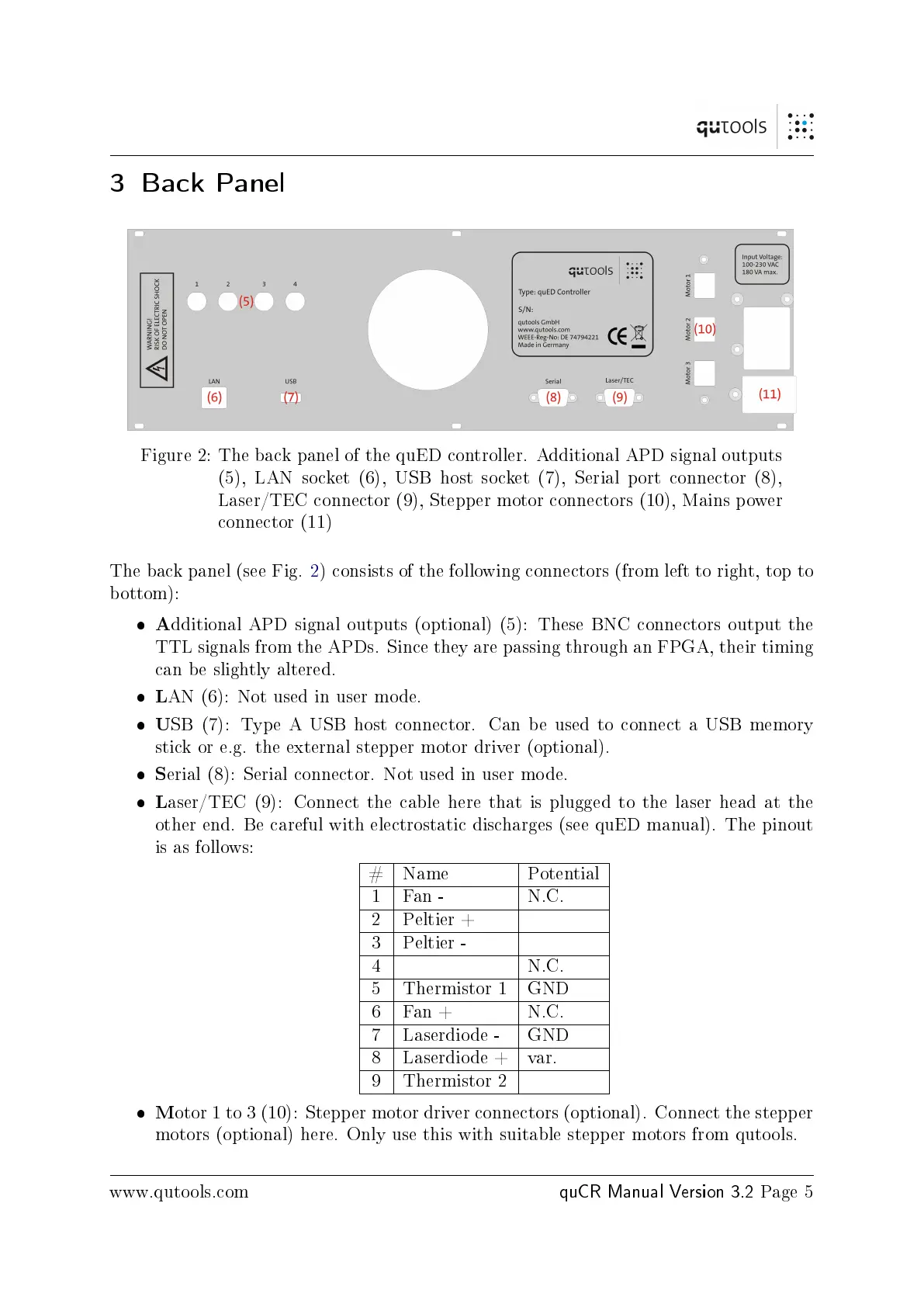
Figure 2: The back panel of the quED controller. Additional APD signal outputs
(5), LAN socket (6), USB host socket (7), Serial port connector (8),
Laser/TEC connector (9), Stepper motor connectors (10), Mains power
connector (11)
The back panel (see Fig. 2) consists of the following connectors (from left to right, top to
bottom):
A
dditional APD signal outputs (optional) (5): These BNC connectors output the
TTL signals from the APDs. Since they are passing through an FPGA, their timing
can be slightly altered.
L
AN (6): Not used in user mode.
U
SB (7): Type A USB host connector. Can be used to connect a USB memory
stick or e.g. the external stepper motor driver (optional).
S
erial (8): Serial connector. Not used in user mode.
L
aser/TEC (9): Connect the cable here that is plugged to the laser head at the
other end. Be careful with electrostatic discharges (see quED manual). The pinout
is as follows:
# Name Potential
1 Fan - N.C.
2 Peltier +
3 Peltier -
4 N.C.
5 Thermistor 1 GND
6 Fan + N.C.
7 Laserdiode - GND
8 Laserdiode + var.
9 Thermistor 2
M
otor 1 to 3 (10): Stepper motor driver connectors (optional). Connect the stepper
motors (optional) here. Only use this with suitable stepper motors from qutools.
www.qutools.com
quCR Manual Version 3.2
Page 5
 Loading...