Do you have a question about the RAB Lighting Mini Sensor and is the answer not in the manual?
Seal arm thread using teflon tape or silicone sealant for proper installation.
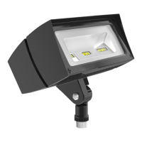
Secure the LED Flood to a 1/2" NPS hole in a junction box or landscape post.
Plug all unused holes and seal threads with silicone for weatherproofing.
The swivel arm allows 140°-150° of vertical aiming adjustment depending on mounting.
Connect the black fixture lead to the (+) LINE supply lead.
Connect the white fixture lead to the (-) COMMON supply lead.
Connect the bare copper ground wire from fixture to supply ground.
Mount wire guard and poly shield with #8-32 screws; align pre-drilled holes.
Verify line voltage at the fixture is correct according to wiring directions.
Ensure the fixture is properly grounded for safety.
Verify if the photocell, if installed, is functioning properly.
Clean the glass lens using a non-abrasive glass cleaning solution.
Do not open the fixture to clean the LED; do not touch the LED.
Details on switching capacity for Relay On/Off and Hi/Lo models.
Information on voltage requirements and power consumption.
Covers detection zone, time adjustment, and auto-testing features.
Features like severe conditions, vandal resistance, surge protection.
Mini Sensor uses SMT for reliability, RF immunity, and compact size.
180° view detects movement along the entire side of a building effectively.
Vandalproof, rainproof, and bugproof design with a molded hard lens.
All wiring must comply with local codes and be done by a qualified electrician.
Turn off power by removing fuse or circuit breaker before installation.
Details on maximum lighting load for different models.
Avoid installing on circuits with Line Carrier Remote Control Systems.
Do not install on circuits feeding motor loads like HVAC or garage openers.
Sensor functions best when movement crosses its pattern, not towards it.
Screw sensor arm into mounting plate for wall or ceiling mount.
Bring power and sensor leads into the box, connect ground, strip insulation.
Twist on wire nuts, seal gasket, fasten plate, screw in bulbs, turn on power.
Diagram for overriding sensor with a manual switch.
Wiring diagram for switching loads exceeding sensor rating using a relay.
Considerations for wiring multiple sensors together.
Avoid installing on circuits with motor loads or voltage variations.
Sensor detects small temperature changes from motion to turn on lights.
Lights stay on as long as motion is detected, adjustable from 5 seconds to 15 minutes.
Sensor may detect large animals; masking can limit detection.
Adjustments for light duration, responsiveness, and daylight deactivation.
Keep lights on by flipping the wall switch twice; resets to auto at dawn.
Choose locations where the sensor can see all illuminated paths of movement.
Describes the 180° detection zone and how to adjust range/width.
A 3-minute test period allows aiming and walk testing of the sensor.
Steps to check and adjust the sensor's coverage pattern.
Guidance on adjusting Sensitivity, Time Control, and Photocell.
Ensure sensor is not aimed at heat sources or moving objects.
Mask lens or adjust sensor to avoid passing car triggers.
Ensure sensor is level and mounted at an optimal height for range.
Check for paint on lens, consider movement direction, and adjust zones.
Check lamps, fixtures, wiring, and power supply are correct.
Ensure photocell is set for darkness and test period is understood.
Check for adjacent lights or reflections affecting sensor operation.
Adjust photocell or mask lens to prevent reflections from causing early shutoff.
Avoid specific lamp types that may cause premature shutoff due to stray light.
Install sensor on a dedicated circuit, free from motor loads.
Do not wire sensors in parallel; test them separately.
Ensure proper distance from lights, avoid reflections, roads, and environmental triggers.
Mount sensor in a protected area to avoid weather-related triggers.
Adjust aiming or mask lens to reduce nuisance triggering by animals.
Check for strong local radio signals that might activate the sensor.
Sensor will be replaced or repaired if defective within 5 years of purchase.
Service for out-of-warranty units requires a description and fee.
RAB Electric is not liable for incidental or consequential damages.
Sensor is designed for detection, not crime prevention; RAB not liable for damages.
Review the Technical Tips sections of the manual before calling.
Call 888 RAB-1000 with unit catalog number and circuit information.
| Brand | RAB Lighting |
|---|---|
| Model | Mini Sensor |
| Category | Security Sensors |
| Language | English |