AL
TM
AREA LIGHT INSTALLATION INSTRUCTIONS
®
Page 2
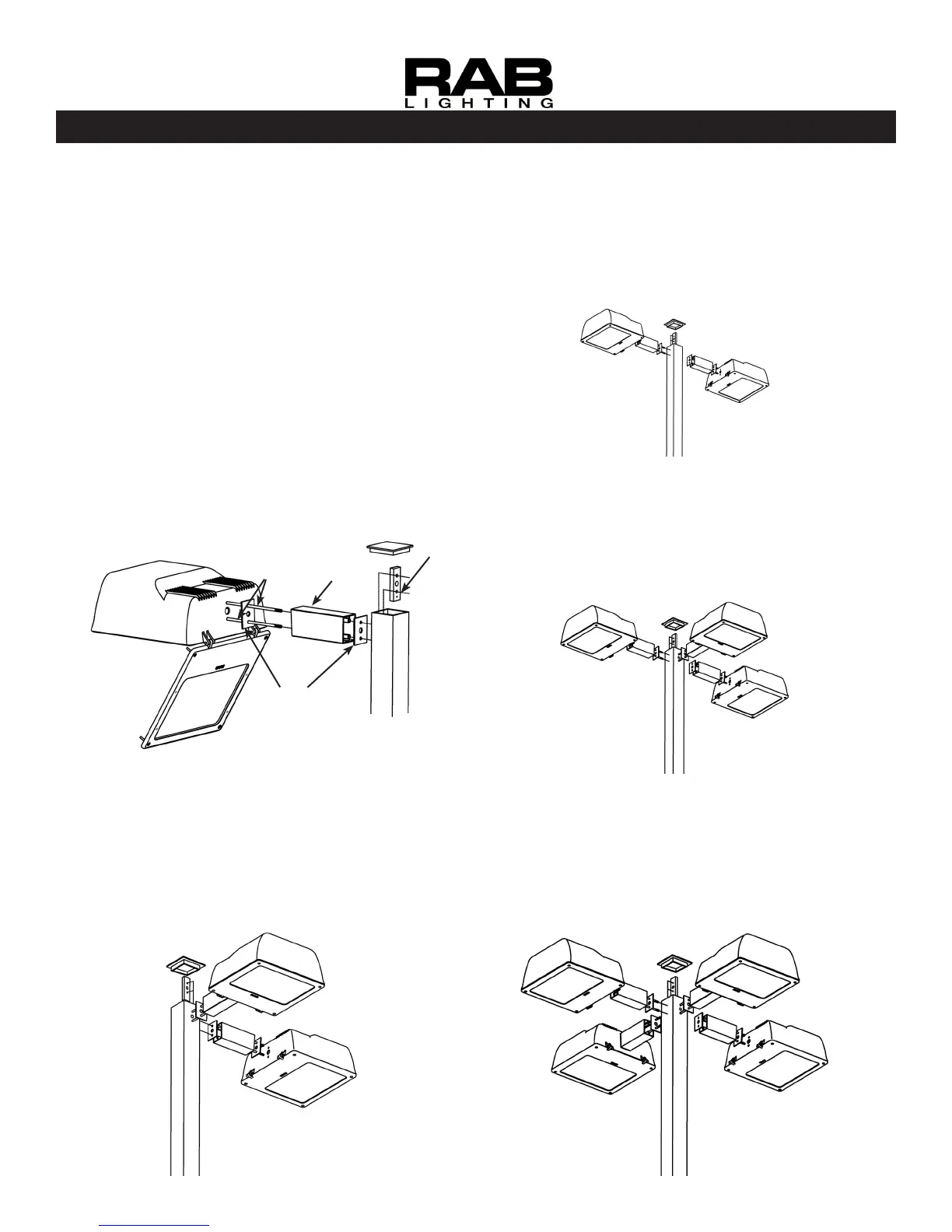
MOUNTING (1) AL fIXTURE
DIRECTLy TO POLE
Fixed Arm mounting directly to 4” or larger square steel
pole. Note Arm Orientation detail on rst page.
Loosen (4) door screws, open xture. Remove
ballast cover.
Insert Threaded Rods into the pole and thread into
the Bolster Plate.
Feed wires from xture through Gasket, Arm and
2nd Gasket and into pole. Make connections and
knot wires as a strain relief. Replace pole cap.
Line up extrusion slots with the Threaded Rods and
slide Arm and xture on Threaded Rods.
Place at washer, lock washer and nut on the
Threaded Rods inside the xture and tighten
securely.
1.
2.
3.
4.
5.
Bolster
Plate
Gaskets (2)
Arm
Threaded
Rods
MOUNTING (2) AL fIXTURES
AT 90° DIRECTLy TO POLE
Fixed Arm direct pole mounting of 2 xtures at 90 de-
grees as shown below.
See steps 1-5 in “MOUNTING (1) AL FIXTURE
DIRECTLY TO POLE” section. Follow for each xture
MOUNTING (2) AL fIXTURES
AT 180° DIRECTLy TO POLE
Fixed Arm direct pole mounting of 2 xtures at 180 de-
grees as shown below.
See steps 1-5 in “MOUNTING (1) AL FIXTURE
DIRECTLY TO POLE” section. Follow for each xture
MOUNTING (3) AL fIXTURES
DIRECTLy TO POLE
Fixed Arm direct pole mounting of 3 xtures.
See steps 1-5 in “MOUNTING (1) AL FIXTURE
DIRECTLY TO POLE” section. Follow for each xture
MOUNTING (4) AL fIXTURES
DIRECTLy TO POLE
Fixed Arm direct pole mounting of 4 xtures.
See steps 1-5 in “MOUNTING (1) AL FIXTURE
DIRECTLY TO POLE” section. Follow for each xture