AL
TM
AREA LIGHT INSTALLATION INSTRUCTIONS
®
Page 3
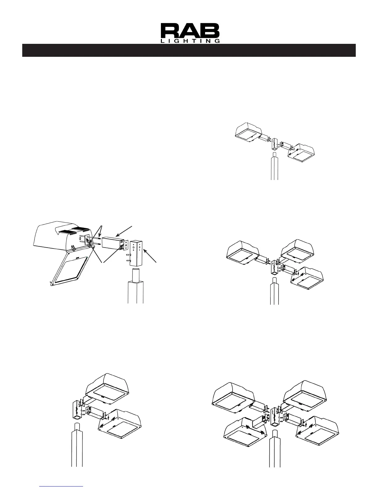
MOUNTING (1) AL fIXTURE TO
BTA ADAPTOR
Fixed Arm mounting to RAB’s pole top adaptor,
Loosen (4) door screws, open xture. Remove
ballast cover.
Insert Threaded Rods into the Adaptor.
Feed wires from xture through Gasket, Arm and
2nd Gasket and into Adaptor. Make connections
and push wires into the adaptor. Wires should be
knotted as a strain relief.
Line up extrusion slots with the Threaded Rods
and slide Arm and xture on Threaded Rods.
Place at washer, lock washer and nuts on
each Threaded Rod inside the xture. Tighten
securely.
Place Adaptor over 2 3/8” Tenon and tighten set
screws on Adaptor.
1.
2.
3.
4.
5.
6.
Adaptor
Gaskets(2)
Arm
Threaded
Rods(2)
MOUNTING (2) AL fIXTURES AT
180° TO BTA ADAPTOR
Fixed Arm mounting to BTA180 for mounting 2 xtures at
180 degrees as shown below.
See steps 1-6 in “MOUNTING (1) AL FIXTURE TO BTA
ADAPTOR” section. Follow for each xture.
MOUNTING (2) AL fIXTURES AT
90° TO BTA ADAPTOR
Fixed Arm mounting to BTA90 for mounting 2 xtures at
90 degrees as shown below.
See steps 1-6 in “MOUNTING (1) AL FIXTURE TO BTA
ADAPTOR” section. Follow for each xture.
MOUNTING (3) AL fIXTURES TO
BTA ADAPTOR
Fixed Arm mounting to BTA3 for mounting 3 xtures as
shown below.
See steps 1-6 in “MOUNTING (1) AL FIXTURE TO BTA
ADAPTOR” section. Follow for each xture.
MOUNTING (4) AL fIXTURES TO
BTA ADAPTOR
Fixed Arm mounting to BTA4 for mounting 4 xtures as
shown below.
See steps 1-6 in “MOUNTING (1) AL FIXTURE TO BTA
ADAPTOR” section. Follow for each xture.