Installation Manual
COMBI - TA05A005.C0604
8
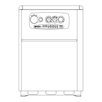
MINIMUM DISTANCES IN mm.
450
60 450 60
C
F
G
A
R
R
C
G
F
A
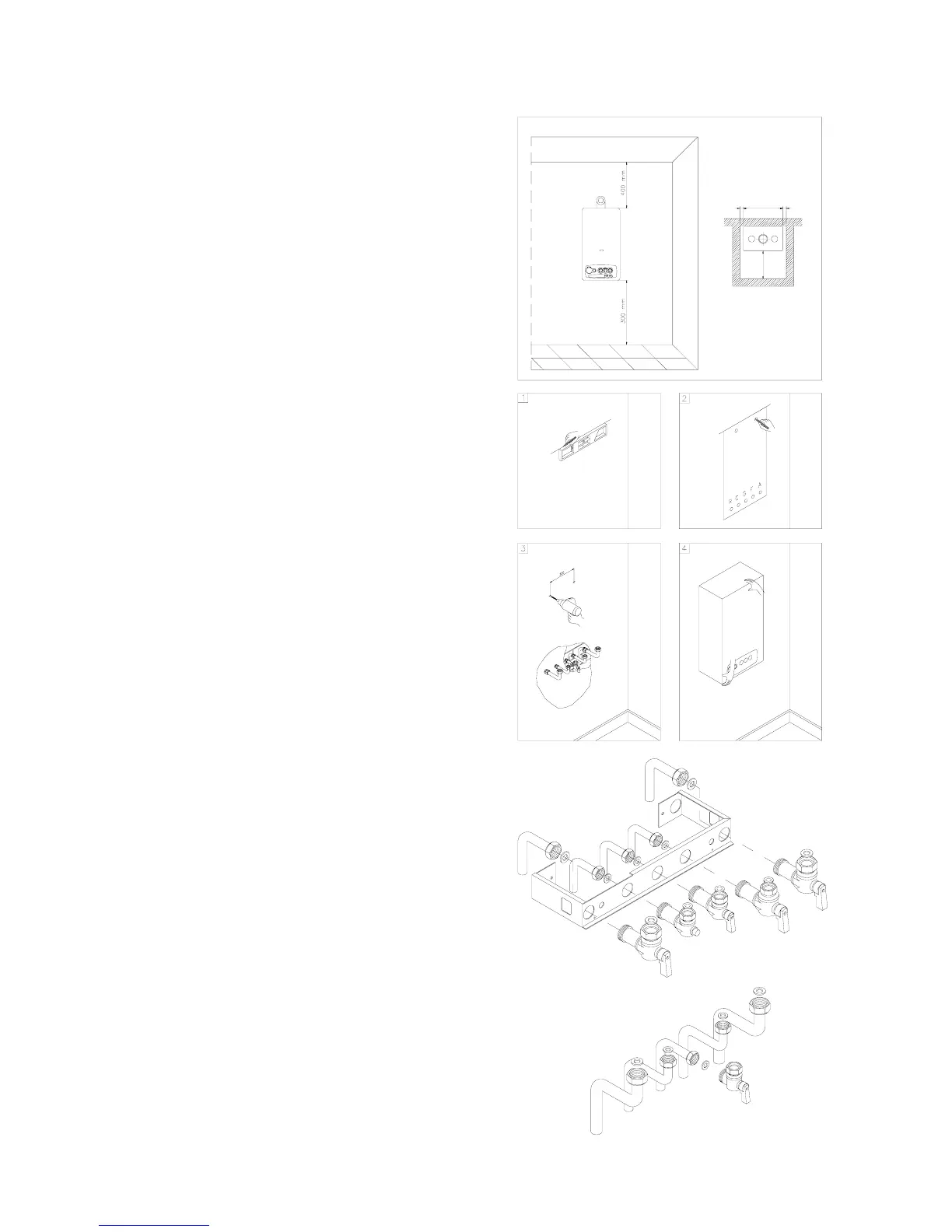
BOILER INSTALLATION - MINIMUM DISTANCES FOR FIXING TO WALL
To allow access inside the boiler for maintenance operations,
the minimum distances shown in fig. 1 must be kept.
To aid installation, the boiler is supplied with a template for
advance location of connections to pipes. In this way, you may
simply hook up the boiler when the wall fixings are completed
(fig.1).
To install the boiler proceed as follows (see fig.2):
1. Use a spirit level (min. 25mm in length) to draw a line on
the wall where the boiler is to be installed.
2. Position the top of the template on the line drawn with the
spirit level, keeping to the recommended distances; now
mark the two points where the two fixing screws or
brackets are to go, then mark the points where the water
and gas connections will go;
3. Take away the template and proceed by connecting up
the connectors supplied with the boiler to the hot and cold
water supplies, gas system and heating pipes;
4. Mount the boiler on the wall using the fixing screws or
brackets and make all necessary pipe connections.
WATER CONNECTIONS
To facilitate installation, the boiler is equipped with a fittings kit
(fig. 3).
IMPORTANT:
Before connecting the heating system pipes, carefully clean
the system to prevent residual dirt from entering into
circulation and negatively affecting boiler function. Install a
funnel with discharge under the safety valve (calibrated to 3
bar) to collect water in case of leaking due to overpressure.
No safety valve is needed for the domestic hot water circuit,
but if the cold main inlet pressure exceeds 5 bar a pressure
reducing value should be fitted.
ADVICE AND SUGGESTIONS FOR DEALING WITH
VIBRATIONS AND NOISE FROM THE SYSTEM
avoid using pipelines of reduced diameter;
avoid the use of tight bends and adapters in important
sections;
clean out the system thoroughly before connecting up the
boiler in order to eliminate any residue left in the pipes and
radiators.
N.B.: Make sure that the water and heating pipes are not
used as earth connections for electrical apparatus.
They are in no way suitable for such purposes
Fig. 1
Fig. 2
FIXING JIG
W/VALVES
FIXING KIT
R RETURN ¾”
C HOT WATER 1/2"
G GAS 1/2"
F COLD WATER 1/2"
A HEATING FLOW ¾”
Fig. 3
 Loading...