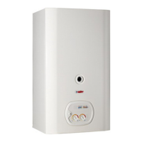
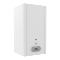
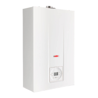
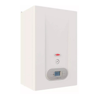
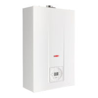
Installation Manual
COMBI - TA05A005.C0604
15
18
3
10
412
5
7
2
11
16
19
6
13
14
15
1
20
9
8
TECHNICAL DATA
DIFFERENTIAL PRESSURE SWITCH FOR FAN CONTROL
To guarantee maximum safety in flue exhaust, a differential pressure switch is installed on the room sealed models. This air
pressure switch automatically controls perfect functioning of the electric fan and the passage of both external air and exhaust flue
pipes.
LIMITER
The boiler is equipped with a variable flow limiter at the cold water inlet. The flow limiter can be adjusted by turning the screw in
order to obtain the correct flow rate of domestic hot water for the specific boiler output.
FLOWSWITCH
This device gives precedence to domestic hot water and is fitted to boilers which supply instantaneous hot water. It allows
conversion to hot water even with a minimum hot water demand (min. 2 litres), using an electromagnetic principle with electrical
switching by means of a relay. The device is made of non-toxic, corrosion-proof ZYTEL 101 L plastic material which has type
approval with non-toxic characteristics and is unaffected by hard water. In addition, a filter is fitted before the flowswitch and at the
cold water inlet which eliminates any water impurities. These features guarantee that the flowswitch operation is highly efficient.
BY-PASS
All boilers are fitted with a by-pass. This element is essential in the following cases:
• if a two-way zone valve is installed
• if thermostat valves are installed in the radiators.
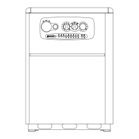
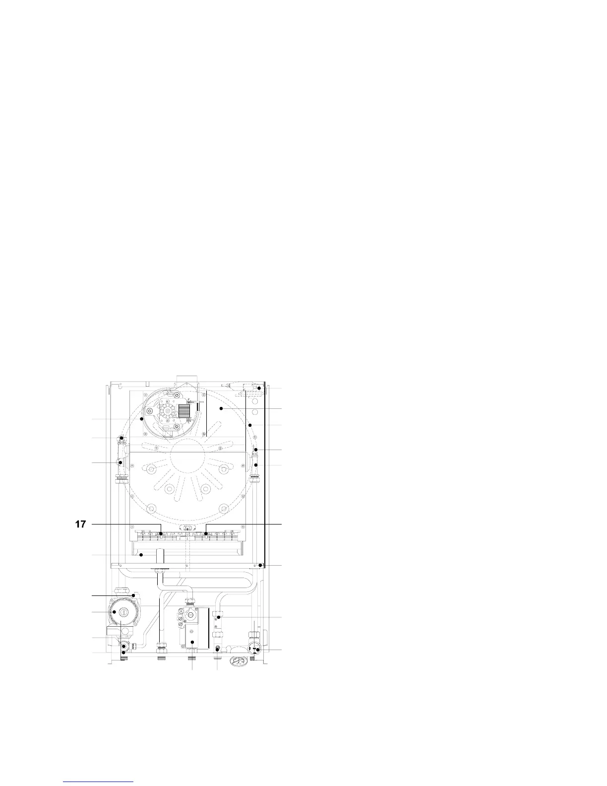
MAIN COMPONENTS
KEY
1.
MAIN HEAT EXCHANGER
2. CIRCULATING PUMP
3. AUTOMATIC AIR VENT
4. GAS VALVE
5. BY-PASS
6. EXPANSION VESSEL
7. 3 BAR SAFETY VALVE
8. BURNER
9. HEATING SENSOR
10. WATER PRESSURE SWITCH
11. ELECTRONIC FLOWSWITCH
12. FLOWSWITCH CONNECTION WITH FLOW LIMITER
13. HOT WATER SENSOR
14. LIMIT THERMOSTAT 90°C
15. FLUE HOOD
16. ROOM-SEALED CHAMBER COVER
17. IGNITION ELECTRODE
18. FLAME IONISATION ELECTRODE
19. AIR PRESSURE SWITCH
20. EXHAUST FAN