Installation Manual
COMBI - TA05A005.C0604
13
REGULATING THE MAX. AND MIN. MODULATION GAS PRESSURE
To regulate the maximum gas pressure to the burner proceed as follows:
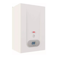
• connect a gauge into the pressure socket B (fig.1).
• remove the aluminium protective cap from screw A (fig.1) counter-clockwise;
• turn the boiler on with the selector turned to the 7 winter position;
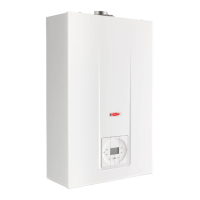
• once ignited, set the "P1 MAX. HEAT" trimmer (fig.2) to the maximum and turn
screw A (fig.1) on the stabiliser clockwise to increase pressure or counter-
clockwise to decrease pressure (see the table below for calibration pressures);
• on completion, screw in the aluminium cap, protecting screw A, previously
removed from the gas valve;
• regulating the min. gas pressure: without removing the gauge and with the
selector set to 7 winter, set the "P1 MAX.
HEAT" trimmer to the minimum heat by turning
it counter-clockwise;
• regulate the minimum pressure by turning the
"P2 MIN. GAS" trimmer (see the table below for
calibration pressures);
• on completion, set the "P1 MAX. HEAT"
trimmer to the require heating load;
• remove the gauge, tighten the pressure socket
B and make sure there are no gas leaks.
N.B. The "P1 MAX. HEAT" trimmer is factory set to
80% of the maximum nominal output during the
testing stage. When the boiler is started up for the
first time is must be regulated according to the
thermal power of the system.
To make adjustments use a flat head screwdriver
and turn clockwise to increase or counter-clockwise
to decrease.
MIN. AND MAX. GAS PRESSURES
Models:
RBS 20 E
NATURAL GAS
G20
LPG 30/31
Max. pressure at burner mbar 11 33
Min.. pressure at burner mbar 2 6
D
B
10
20
30
40
A
PRESSURE GANGE
GAS VALVE VK4105G1005
C
MAX.HEAT.
P1
MIN.GAS
P2
Fig. 1
Fig. 2