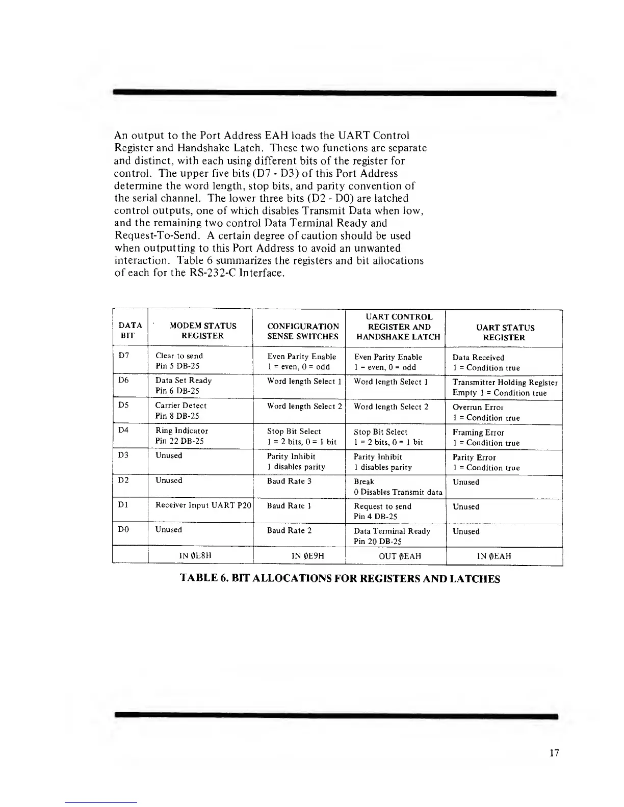
An output to the Port
Address
EAH
loads the
UART Control
Register
and Handshake Latch. These two functions are separate
and
distinct, with
each using different
bits
of the register for
control. The upper five
bits
(D7
-
D3) of
this Port Address
determine the word length,
stop bits, and parity
convention of
the serial channel. The lower
three
bits
(D2
-
DO)
are
latched
control outputs, one of which
disables Transmit Data when
low,
and the remaining
two control Data Terminal Ready
and
Request-To-Send.
A
certain degree of caution should
be
used
when outputting
to this Port Address
to avoid an
unwanted
interaction.
Table 6 summarizes
the registers and bit allocations
of
each for the
RS-232-C Interface.
DATA
BIT
MODEM
STATUS
REGISTER
CONFIGURATION
SENSE
SWITCHES
UART
CONTROL
REGISTER AND
HANDSHAKE
LATCH
UART STATUS
REGISTER
D7 Clear
to send
Pin 5 DB-25
Even Parity
Enable
1
=
even,
=
odd
Even
Parity Enable
1
=
even,
=
odd
Data Received
1
=
Condition
true
D6
Data Set Ready
Pin
6
DB-25
Word
length Select
1
Word
length Select
1
Transmitter
Holding Register
Empty
1
=
Condition true
D5
Carrier Detect
Pin
8 DB-25
Word length
Select
2
Word length Select
2
Overrun Error
1
=
Condition
true
D4
Ring
Indicator
Pin
22 DB-25
Stop Bit
Select
1
=
2
bits,
=
1 bit
Stop Bit Select
1
=
2 bits,
=
1 bit
Framing
Error
1
=
Condition
true
D3
Unused
Parity
Inhibit
1
disables
parity
Parity Inhibit
1
disables
parity
Parity
Error
1
=
Condition
true
D2
Unused
Baud Rate
3 Break
Disables Transmit
data
Unused
Dl
Receiver
Input
UART
P20 Baud
Rate
1
Request
to send
Pin
4
DB-25
Unused
DO
Unused
Baud Rate
2
Data Terminal
Ready
Pin
20
DB-25
Unused
IN
0E8H
IN 0E9H
OUT
0EAH IN 0EAH
TABLE
6. BIT ALLOCATIONS
FOR REGISTERS
AND
LATCHES
17

 Loading...