ADDRESS DECODER
As shown
in
Figure
2,
the TRS-80 is memory
mapped.
Therefore,
the address
01AC
(in
HEX)
is in
the ROM
part
of the map. Address 380A is
in the keyboard area
and
3CAA
accesses the video display RAMs.
Since the data and
address buses are connected
in parallel to all the sections,
there must be some
method to determine which
section is
being
accessed. A decoding network
monitors the higher
order address bits and selects which
"memory" the
CPU
wants to use. The address
decoder is so important
to
the
operation
of the system that it has been redrawn
in
Figure
3. Keep
your
schematic
handy since there
are
signals shown
in
Figure
3 that need to be sourced
or traced.
The
address decoder uses six bits. A10
through A15 are
needed plus RD* and
RAS* (RAM Address Select). A1
5 is
the most
significant bit of the address bus. Let's combine
the six high order bits and add a
couple
more, so that we
have
two hex
digits:
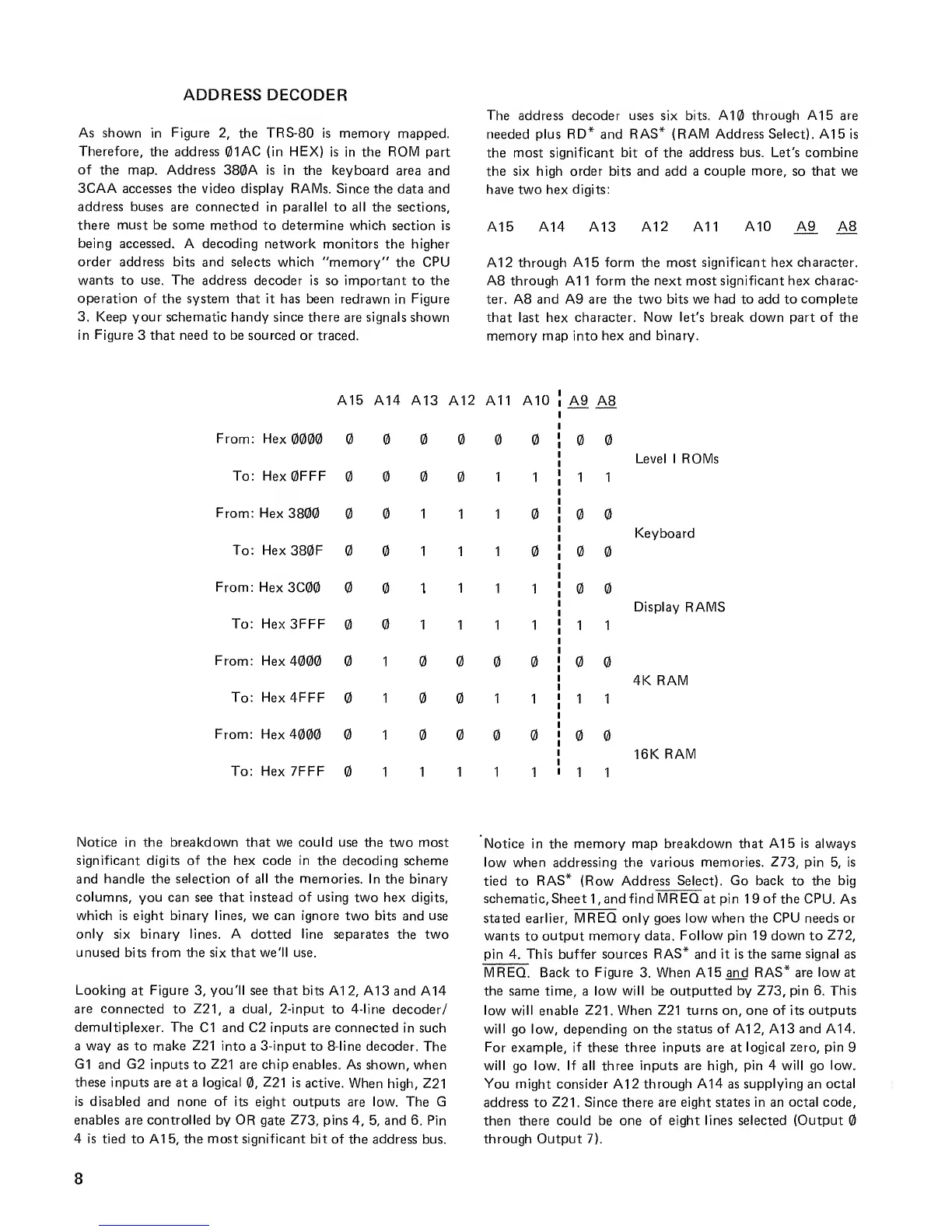
A15
A14 A13 A12 A11 A10
A9
A8
A12 through
A15
form
the most significant hex character.
A8
through A1 1 form the
next most significant hex charac-
ter. A8 and A9 are the two
bits we
had to add to
complete
that last hex character.
Now let's
break down part of the
memory map into
hex and binary.
A15 A14 A13
A12 A11
From: Hex
0000
00000
To: Hex0FFF
1
From: Hex
3800 111
To: Hex380F
111
From: Hex
3C00
111
A10
To: Hex3FFF
1 1
From: Hex
1
1
From: Hex
4000 10
To:
Hex4FFF
10
1
To: Hex 7FFF
1111
1
1
1
1
A9 A8
1
1
1 1
1
1
1
1
Level I ROMs
Keyboard
Display RAMS
4K RAM
16K
RAM
Notice in the breakdown that we could use the
two most
significant digits of the
hex
code in the decoding
scheme
and
handle the selection of all the
memories. In the binary
columns,
you can see that
instead
of
using
two hex digits,
which is eight binary lines, we can ignore two bits
and
use
only
six
binary lines. A
dotted
line
separates the two
unused bits from the six that we'll use.
Looking
at
Figure
3,
you'll see that bits A12, A13
and A14
are connected
to Z21, a dual, 2-input to 4-line
decoder/
demultiplexer. The
C1 and C2 inputs are connected
in such
a way as to make Z21 into
a
3-input
to 8-line decoder.
The
G1
and
G2
inputs to Z21 are chip enables. As
shown, when
these
inputs are at a logical
0,
Z21
is active.
When
high, Z21
is disabled and none of
its eight outputs are low. The G
enables are controlled by OR
gate
Z73, pins
4, 5,
and 6. Pin
4 is tied
to A1
5,
the most significant
bit
of
the address
bus.
Notice in the memory map breakdown that
A15
is always
low when addressing the various
memories. Z73,
pin
5,
is
tied
to
RAS* (Row Address
Select). Go back
to
the big
schematic. Sheet
1
, and find
I
stated earlier.
IREQatpin
19 of the CPU.
As
1REQ
only goes low when the
CPU
needs or
wants
to
output memory data.
Follow
pin
19 down
to
Z72,
pin 4.
This
buffer
sources RAS* and it is the same signal as
MREQ. Back to
Figure
3. When A15and RAS* are
low at
the
same time, a
low will be outputted by Z73, pin 6. This
low will enable Z21. When Z21 turns on, one of its
outputs
will
go low, depending
on the status of A12, A13 and A14.
For example, if these three inputs are at
logical zero,
pin 9
will
go
low. If all three
inputs
are high,
pin 4 will
go
low.
You might consider A12 through
A14
as
supplying
an
octal
address to
Z21. Since
there
are eight states in an octal code,
then there
could be one of eight lines selected (Output
through Output 7).
8

 Loading...


