~
.....
~
COMPUTCR'C"CTS"'
RADIO SHACK
TRS·SO
~.
'_
lC_III_/""\
__
'_
' M
....
O
..
D
..
E_L_I_L
..
EV_E_L
..
I
..
I_
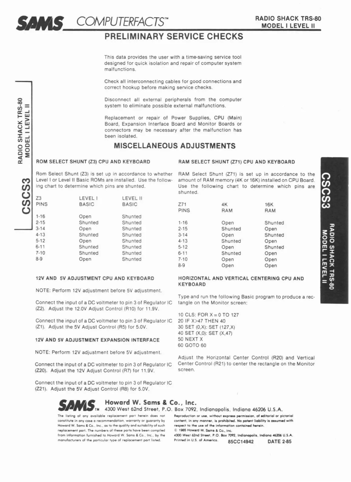
PRELIMINARY SERVICE CHECKS
This data provides the user
with
a time-saving service
tool
designed for
quick
isolation
and repair of
computer
system
malfunctions.
Check all
interconnecting
cables
for
good
connections
and
correct
hookup
before making service checks.
MISCELLANEOUS ADJUSTMENTS
Disconnect all external peripherals from
the
computer
system
to
eliminate possible external
malfunctions.
Replacement
or
repair
of
Power Supplies,
CPU
(Main)
Board, Expansion Interface Board and
Monitor
Boards or
connectors
may be necessary
after
the
malfunction
has
been isolated.
RAM SELECT SHUNT
(Z71)
CPU
AND KEYBOARD
Type and run the
following
Basic program
to
produce a rec-
tangle on the
Monitor
screen:
HORIZONTAL AND VERTICAL CENTERING
CPU
AND
KEYBOARD
RAM Select Shunt
(Z71)
is set up in accordance
to
the
amount of RAM memory (4K or 16K) installed on
CPU
Board.
Use
the
following
chart
to
determine which pins are
shunted.
10
CLS: FOR X =0 TO
127
20
IF X>47 THEN
40
30
SET
(O,X):
SET (127,X)
40 SET
(X,O):
SET (X,47)
50 NEXT X
60 GOTO 60
ROM
SELECT SHUNT
(Z3)
CPU
AND KEYBOARD
NOTE: Perform
12V
adjustment
before
5V
adjustment.
Z3
LEVELl
LEVEL
II
PINS BASIC BASIC
271
4K 16K
PINS
RAM
RAM
1-16
Open Shunted
2-15
Shunted
Shunted
1-16
Open Shunted
3-14
Open Shunted 2-15
Shunted
Open
4-13
Shunted Shunted 3-14
Open
Shunted
5-12
Open Shunted 4-13
Shunted Open
6-11
Shunted
Shunted 5-12
Open Shunted
7-10
Shunted Shunted
6-11
Shunted Open
8-9
Open Shunted 7-10
Open Open
8-9 Open
Open
12V AND
5V
ADJUSTMENT
CPU
AND KEYBOARD
Connect the
input
of
a
DC
voltmeter
to
pin 3 of Regulator IC
(Z2).
Adjust
the 12.0V
Adjust
Control (Rl0)
for
11.9V.
Connect the
input
of a
DC
voltmeter
to
pin 3 of Regulator IC
(Z1).
Adjust
the
5V
Adjust
Control
(R5)
for
5.0V.
12V AND
5V
ADJUSTMENT EXPANSION INTERFACE
Rom Select Shunt
(Z3)
is set up in accordance
to
whether
M Level I
or
Level
II
Basic ROMs are installed. Use the follow-
.
CJ)
ing chart
to
determine which pins are shunted.
()
CJ)
()
o
co
ch=
a:...J
....
w
::.::>
()~
«-
~...J
CJ)w
0
0
-0
o~
«
a:
NOTE: Perform 12V
adjustment
before
5V
adjustment.
Connect
the
input
of
a
DC
voltmeter
to
pin 3
of
Regulator IC
(Z20).
Adjust
the
12V
Adjust
Control
(R7)
for
11.9V.
Adjust
the Horizontal Center Control (R20) and Vertical
Center Control
(R21)
to
center the rectangle on the
Monitor
screen.
Connect
the
input
of
a
DC
voltmeter
to
pin 3
of
Regulator IC
(Z21).
Adjust
the
5V
Adjust
Control
(R8)
for 5.0V.
s
I~
Howard
W.
Sams & Co., Inc.
lelrTII
4300
West
62nd Street, P.O. Box 7092,
Indianapolis,
Indiana
46206 U.S.A.
DATE
2-85
85CC14942
R_oductlon
0.-
.....
without
_p'."
pennl
..
lon.
01
edltoriol
0.-
picto.-lol
conl..,t,
In
ony
manner.
i.
prohibited. No pot..... liobUlty
I.
auumed
with
r.sp«'
to
the u
..
of the Infarmotlon contolned
"-<eln.
~
11185
Howanl
W.
Sam.
& Co.,
Inc:.
4300 W
..
, 62nd
St,
..
t. P.O.
lax
7092. Indianapolis. Indiana
~
U.S.A.
Printed
In
U.S.
of
"memo.
Th.
lI,ting of
any
ovailable
r.plocement
port tMreln
does
not
constitute
in
any
cos.
0 rec:ommeondotion.
warranty
or
guaranty
by
Howard W.
Saml
& Co
.•
Inc
..
as
to
the
quality
and
suitability
of such
r.ploc.ment
port. The
numbers
of
the,.
pam
hove
been compiled
from information furnished to Howard
W.
$oms & Co..
Inc
.. by the
manufacturers
of
the
particular
type
of
replocement
port
listed.
 Loading...