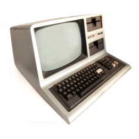
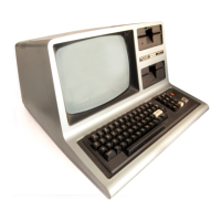
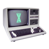
Do you have a question about the Radio Shack TRS-80 III and is the answer not in the manual?
Instructions for safely removing the computer case, including screw locations and handling.
Steps to disconnect and remove the CPU board, including cable management and mounting brackets.
Instructions for disconnecting interconnect cables and removing the main power supply unit.
Detailed instructions for reassembling the computer components in reverse order.
Details the Z-80 CPU, its clock speed, and associated buffering components.
Describes the RAM configuration, addressing, and interfacing with the data bus.
Explains how address decoding selects system I/O ports, ROMs, Keyboard, Video, and RAM.
Provides a map of memory addresses, descriptions, and sizes for the Model III.
Details the input/output ports for peripherals like LPIN, LPOUT, DISKIN, RS232IN, etc.
Describes the video section, including RAM, oscillator, character generation, and wait logic.
Explains the I/O Bus structure and its signals for device interfacing.
Elaborates on the I/O bus design, addressing, data transfer, and control lines for external devices.
Introduction to the floppy disk interface, covering its function, encoding, and components.
Identifies the 1793 as the MOS LSI chip for floppy disk control and lists its port addresses.
Explains the RS-232C option board, its functions, and the TR1602 UART.
Overview of port assignments and bit definitions for the RS-232C interface.
Describes the specifications of the 40-watt switching power supply, including input and output connections.
Introduces the troubleshooting section for the power supply.
Lists the necessary equipment for power supply testing.
Instructions for performing a visual inspection of the power supply for damaged components.
Provides steps to diagnose and resolve issues when the power supply has no output.
Outlines the performance tests to be conducted on the power supply, including input and load conditions.
Outlines adjustments for focus, vertical size, horizontal linearity, width, centering, and horizontal hold.
Provides a checklist for inspecting the disk drive before applying power.
Details the write electronics, winding, and conditions required for data recording.
Describes the read electronics, including amplifier, filter, differentiator, and comparator.
Details the operational signals and procedures for the disk drive.
Provides procedures for maintaining and troubleshooting the disk drive.
Recommends periodic cleaning of the magnetic recording head for optimal performance.
Provides instructions for cleaning the magnetic recording head using isopropyl alcohol.
Lists the equipment required for disk drive alignment and adjustment procedures.
Details the procedure for adjusting the long-term motor speed.
Describes the process of aligning the head radially and checking the "cat eyes" pattern.
Details the adjustment procedure for the track 00 switch and stop adjustment.
Explains how to adjust the index sector timing using a scope.
Instructions for checking and adjusting head amplitude and compliance.
Steps for formatting and backing up a diskette as a final check.
| Brand | Radio Shack |
|---|---|
| Model | TRS-80 III |
| Category | Desktop |
| Language | English |