PREVENTIVE MAINTENANCE
To ensure
that
the
Disk
Drive
operates at its design poten-
tial,
the
only scheduled preventive maintenance required
is
periodic cleaning
of
the magnetic recording head.
Mechanical and electrical adjustment details are provided
for further service
as
a result
of
disassembly
or
repair.
CLEANING THE
HEAD
To clean the magnetic head,
use
a lint-free cloth
or
cotton
swab moistened with
91%
Isopropyl alcohol.
Wipe
the head
carefully
to
remove
all
accumulated oxide and dirt.
Dry
the
head using a lint-free cloth.
CAUTION: Rough or abrasive cloth should not
be
used
to
clean
the
magnetic recording head.
Use
of
cleaning solvents
other than
91
% Isopropyl alcohol may damage
the
head.
Extreme care must
be
exercised
to
prevent the heads from
being damaged (i.e., scratching, banging together, etc.).
ALIGNMENT AND ADJUSTMENT
To perform the alignment and adjustment procedures,
you
will
require the following equipment:
* 30
MHz
Dual
Trace Triggered Sweep Scope
* 5
1/4"
Alignment Diskette
* 5 1
/4"
Blank "scratch" Diskette
DRIVE MOTOR MAINTENANCE
Long
Term Motor Speed Adjustment
1. Check power
to
unit. (+12
VDC
+
@.6V,
and
+5
VDC
±
@.25V.)
2. Insert a blank diskette and activate the drive.
3. Under fluorescent lighting, observe the speed disk
on the spindle pulley. For 60
Hz
operation
the
outer ring on the speed disk should appear station-
ary. For
5@
Hz
operation the inner ring should
appear stationary.
4.
If
the
speed disk does not appear stationary, adjust
R4, located on the Servo
PCB,
until
the
disk
appears stationary.
5.
If
motor speed cannot
be
adjusted, repair Servo
PCB
or motor
as
required.
108
Instantaneous Speed Variation Check/RAW Data Check
1.
With
a blank diskette inserted, write a 2F pattern
on any track.
2. Connect scope
to
TP 5 with:
Vert.
to
2 volts/div.
Time
Base
to
1,usec/div.
Trigger internal/positive
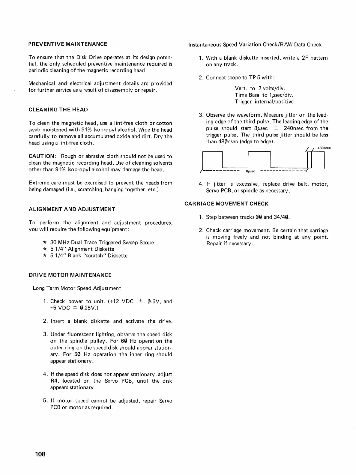
3. Observe
the
waveform. Measure jitter
on
the lead-
ing
edge
of
the
third pulse. The leading edge
of
the
pulse should start
8,usec
± 240nsec from
the
trigger pulse. The third pulse jitter should
be
less
than 480nsec (edge to edge).
lflre,
L--J-----
L,
__
J _
4.
If
jitter
is
excessive, replace drive belt, motor,
Servo
PCB,
or spindle
as
necessary.
CARRIAGE MOVEMENT CHECK
1. Step between tracks
00
and 34/40.
2. Check carriage movement.
Be
certain
that
carriage
is
moving freely and not binding at any point.
Repair
if
necessary.

 Loading...