FUNCTIONAL SPECIFICATIONS
The power supply for
the
TRS-80 Model
III
is
a 40
watt,
switching power supply. The printed circuit board
is
mounted
directly
to
the
case.
line
input
to
the
power supply
is
made
through a locking 2-pin
PCB
socket header (SK-1).
2. 0 - 140V Variable Transformer (Variac) -
Used
to
vary input voltage. Recommend
10
Amp,
1.4
KVA
rating minimum.
3.
Voltmeter-
Needed
to
measure
DC
voltages
to
50
VDC
and
AC
volt-
ages
to
200 V
AC.
Recomm~d
two digital multimeters.
Pin
1
Pin
2
line
- Neutral
line
- live
4.
Oscilloscope-
Need
X10 and X100 probes.
Outputs are taken from locking 4-pin
PCB
socket headers
(SK-2, SK-3, and SK-4).
Pin
1 -12V
Pin
2 +12V
Pin
3 Common
Pin
4 +5V
In
theory,
the
power supply rectifies the
AC
line to
DC
and chops it at 20 kHz. The chopped
DC
voltage
is
then
transformed
to
the
required
output
voltages and rectified
to
low voltage isolated
DC.
Feedback loops are provided for
voltage regulation and overcurrent protection.
The power supply module can withstand
the
following
maximum ratings:
Vin
(AC
continuous)
-95
to
135VAC @ 60
Hz
Short Circuit, any
output
- indefinite
TROUBLESHOOTING
Section 1
EQU
IPMENT
FOR TEST SET-UP
1. Isolation Transformer (minimum
of
500VA rating) -
Dangerously
high
voltages are present
in
th
is
power supply. For the safety
of
the individual
doing the testing, please
use
an
isolation
transformer. The 500VA rating
is
needed
to
keep the
AC
waveform from being clipped
off at
the
peaks. These power supplies have
peak charging capacitors and draw full power
at the peak
of
the
AC
waveform.
5. Load Board with Connectors -
See Table 1 for values
of
loads required. The entry on
the table for Safe Load Power
is
the minimum power
ratings for the load resistors used.
6. Ohmmeter
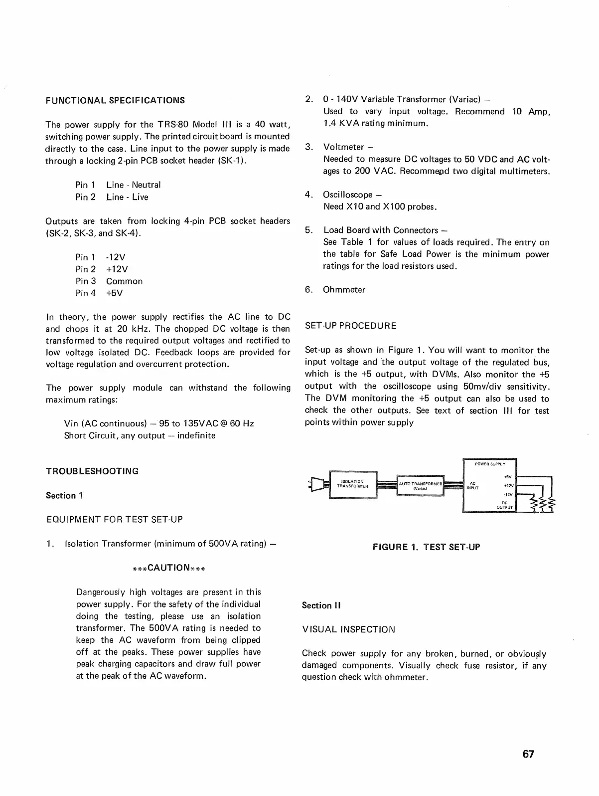
SET·UP PROCEDURE
Set-up
as
shown
in
Figure 1. You
will
want
to
monitor
the
input voltage and 'the
output
voltage
of
the regulated bus,
which
is
the
+5
output,
with
DVMs.
Also monitor
the
+5
output
with the oscilloscope using 50mv/div sensitivity.
The
DVM
monitoring the
+5
output
can also be used
to
check the
other
outputs.
See
text
of section III for test
points within power supply
POWER SUPPLY
AC
INPUT
,12V
OC
OUTPUT
FIGURE 1. TEST SET-UP
Section
II
V
ISUAL
INSPECTION
Check power supply for any broken, burned,
or
obviou?ly
damaged components. Visually check fuse resistor,
if
any
question check with ohmmeter.
67

 Loading...