TRACK
00
ALIGNMENT
Track 00 Switch Adjustment
1. Connect Scope:
Channel A to
pin
1
of
Plug
11
Vert.
to
2 volts/div.
Time
Base
to
10msec.
Trigger internal channel
A,
DC
coupled
2. Step between tracks
02 and 03.
3. Loosen track 00 switch mounting screw and adjust
until switch activates between tracks
02 and 03.
Tighten mounting screw.
Track
G0
Stop Adjustment
1. Connect scope
as
in
Head
Radial alignment.
2. Insert alignment diskette and read track
00.
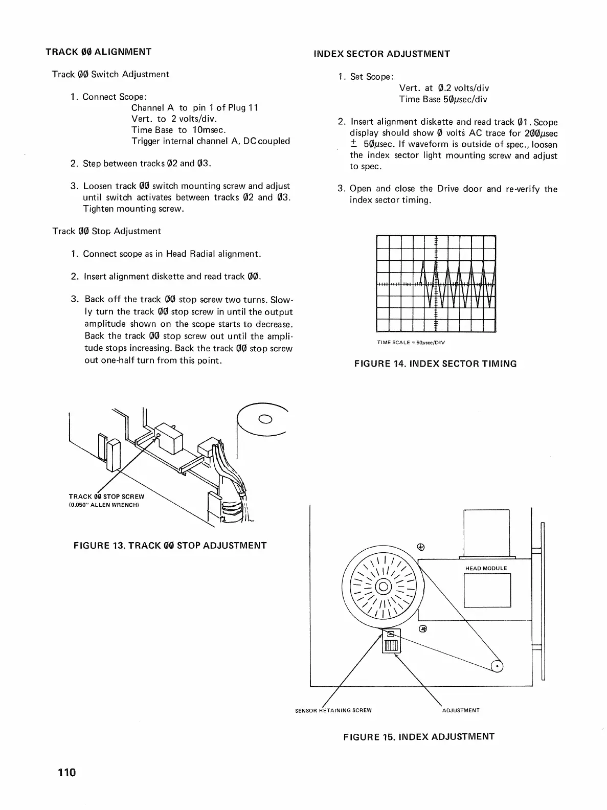
3. Back
off
the track
GG
stop screw two turns. Slow-
ly
turn the track
ctlctl
stop screw
in
until
the
output
amplitude shown on
the
scope starts
to
decrease.
Back
the
track
ctlctl
stop screw
out
until
the
ampli-
tude stops increasing.
Back
the
track
ctlctl
stop screw
out
one-half turn from this point.
FIGURE 13.
TRACK
00
STOP
ADJUSTMENT
INDEX
SECTOR ADJUSTMENT
1. Set Scope:
Vert. at
0.2 volts/div
Time
Base
5ctlJ1sec/div
2. Insert alignment diskette and read track
ctl1
. Scope
display should show
ctl
volts
AC
trace for
2(3ctlJ1sec
±.
5ctlJ1sec.
If
waveform
is
outside
of
spec., loosen
the index sector light mounting screw and adjust
to
spec.
3.
Open and close the Drive door and re-verify the
index sector timing.
j
J
j
j j
\
~~
U\'l
n
!\f
V V
Y
V
YY
TIME
SCALE = 50j.lsec/DIV
FIGURE 14.
INDEX
SECTOR
TIMING
SENSOR
RETAINING
SCREW
ADJUSTMENT
110
FIGURE 15.
INDEX
ADJUSTMENT

 Loading...