SERVICE ADJUSTMENTS
NOTE: Measurements should be made using 12.0
VDC
input.
Measurements with kine (CRT) attached
will
require
the
ground strap from kine be connected
to
chassis
to
prevent
transistor failures
in
the event
of
kine arcing.
FOCUS
Adjust focus control F524 (Figure 1
f Zone 2-A) for best
overall focus.
VERTICAL SIZE
Adjust vertical size control R617 (Figure 1
f Zone 3-8)
to
produce vertical scan
of
approximately 6 inches.
HORIZONTAL LINEARITY
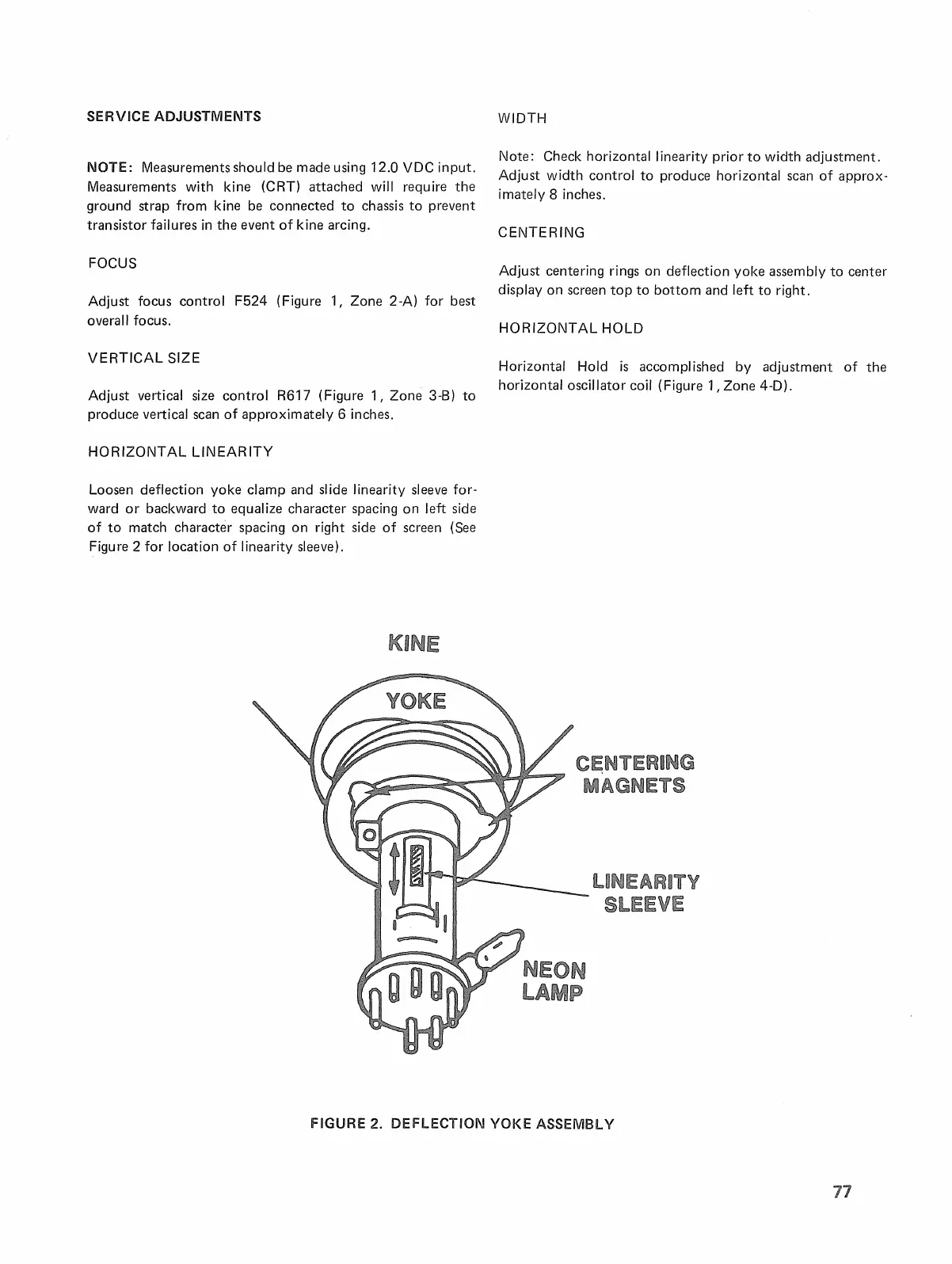
Loosen deflection yoke clamp and slide linearity sleeve for-
ward
or
backward
to
equalize character spacing on left side
of
to
match character spacing on right side
of
screen (See
Figu
re
2 for location of Iinearity sleeve).
WIDTH
Note: Check horizontal linearity prior
to
width adjustment.
Adjust width control
to
produce horizontal scan of approx-
imately 8 inches.
CENTERING
Adjust centering rings on deflection yoke assembly
to
center
display on screen
top
to
bottom and left to right.
HORIZONTAL HOLD
Horizontal Hold
is
accomplished by adjustment of the
horizontal oscillator coil (Figure 1
f Zone
4-0).
FIGURE 2. DEFLECTION YOKE ASSEMBLY

 Loading...