^iruojiJTrijiJiJTJij-LruTjijTri
<~
3
579545 MHz
894888 MH*
VDG
RAM ACCESS
CPU RAM ACCESS
VDG
COLUMN ADDRESS
CPU
ROW ADDRESS
CPU
COLUMN ADDRESS
VDG
ROW
I
I
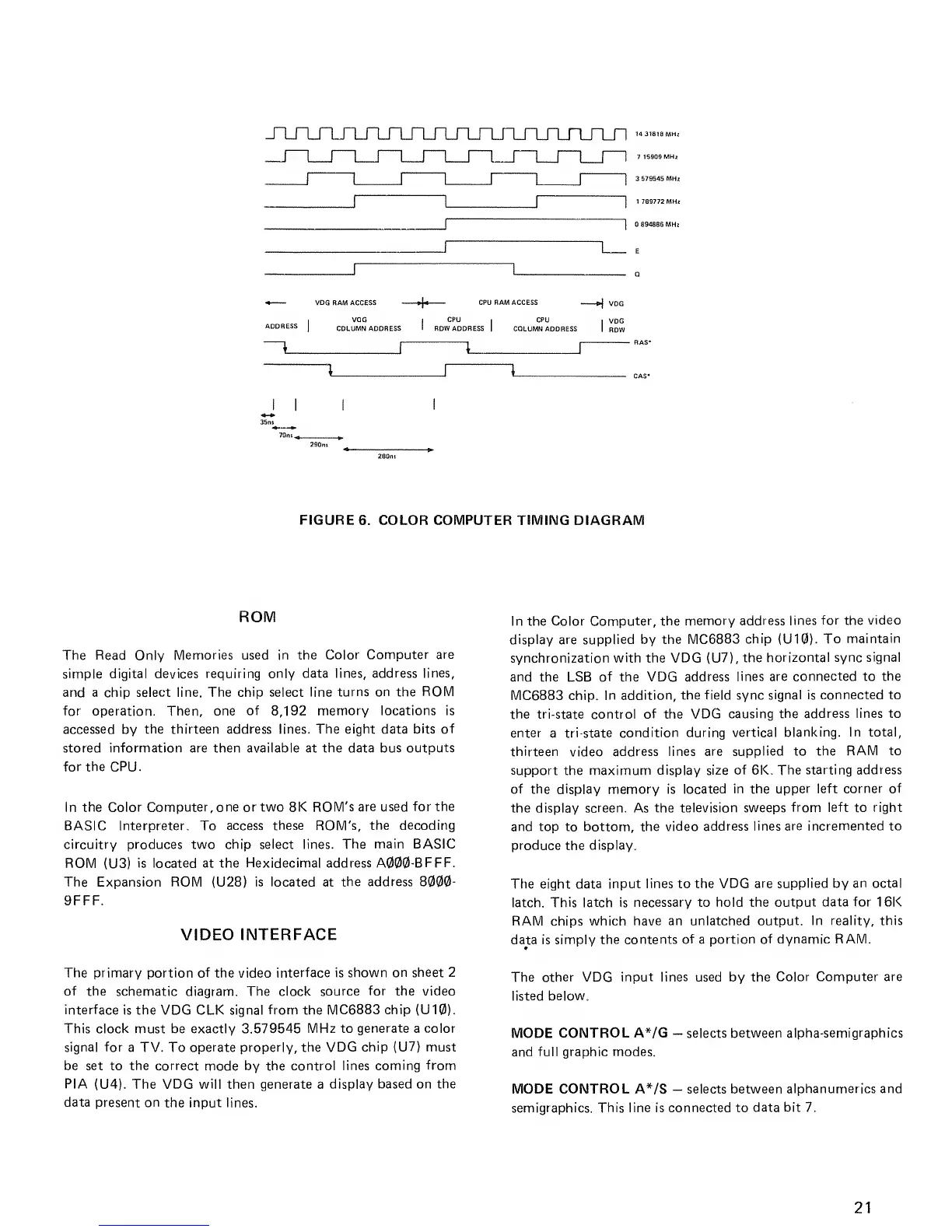
FIGURE
6. COLOR
COMPUTER TIMING
DIAGRAM
ROM
The Read Only
Memories used in the
Color
Computer are
simple digital devices requiring
only data lines,
address lines,
and a chip select line. The
chip
select
line
turns on
the
ROM
for operation. Then, one
of
8,192
memory locations is
accessed
by
the thirteen address lines. The eight data
bits of
stored information are then available at the data bus
outputs
for the CPU.
In the
Color Computer, one or two 8K ROM's
are used for the
BASIC Interpreter. To
access these ROM's, the
decoding
circuitry produces two chip select lines. The
main BASIC
ROM
(U3)
is located at the Hexidecimal address
A000-BFFF.
The Expansion ROM (U28) is
located
at
the address
8000-
9FFF.
VIDEO
INTERFACE
The
primary portion of
the video
interface is shown
on sheet 2
of the
schematic diagram. The clock
source
for
the
video
interface
is the VDG CLK signal
from
the
MC6883 chip (U10).
This clock must be exactly 3.579545
MHz to
generate
a color
signal for
a TV. To
operate properly,
the
VDG
chip
(U7) must
be set to the correct
mode
by the control lines
coming from
PIA
(U4). The VDG
will
then generate a
display based on the
data
present
on
the
input lines.
In the Color Computer,
the memory
address lines
for
the
video
display are supplied by the MC6883
chip
(U10).
To
maintain
synchronization
with
the VDG (U7),
the
horizontal sync
signal
and
the LSB
of
the
VDG address
lines are connected to
the
MC6883 chip.
In addition, the field sync
signal is connected to
the tri-state control
of
the VDG
causing the address lines to
enter
a
tri-state
condition during vertical
blanking. In total,
thirteen
video
address lines
are supplied to the
RAM to
support
the maximum
display size of 6K. The
starting address
of the display memory is located
in the upper left
corner of
the display screen. As
the television sweeps
from left to right
and top to bottom, the
video address
lines are incremented to
produce
the
display.
The eight
data input lines to the VDG
are supplied by
an octal
latch.
This latch is necessary to hold the
output data for
16K
RAM chips which
have an unlatched
output. In reality, this
data is simply
the contents
of
a
portion of dynamic RAM.
The other VDG
input lines
used by the
Color Computer are
listed below.
MODE
CONTROL A*/G
-
selects between alpha-semigraphics
and full graphic
modes.
MODE CONTROL A*/S
-
selects between
alphanumer ics and
semigraphies. This line is connected to
data bit 7.
21
 Loading...