Power Supply
Plug the battery eliminator into
a
1
20 VAC outlet
and into the
miniature
power jack on
the
board
and check
the output
at
the
miniature power
jack for
DC output
using the
oscilloscope. The minimum
instantaneous voltage
frojii the
battery
eliminator, the
lowest
voltage point
on its
output
waveform,
must be
14.5
volts or
greater.
If the output
dips
below 14.5 volts, the
analog circuitry will
be affected
by
noise
on the internal
power supply lines
as
the voltage
drops out of regulation.
Change
battery
eliminator
to see if
this
cures the problem. If not. the problem
may be the
voltage
regulator
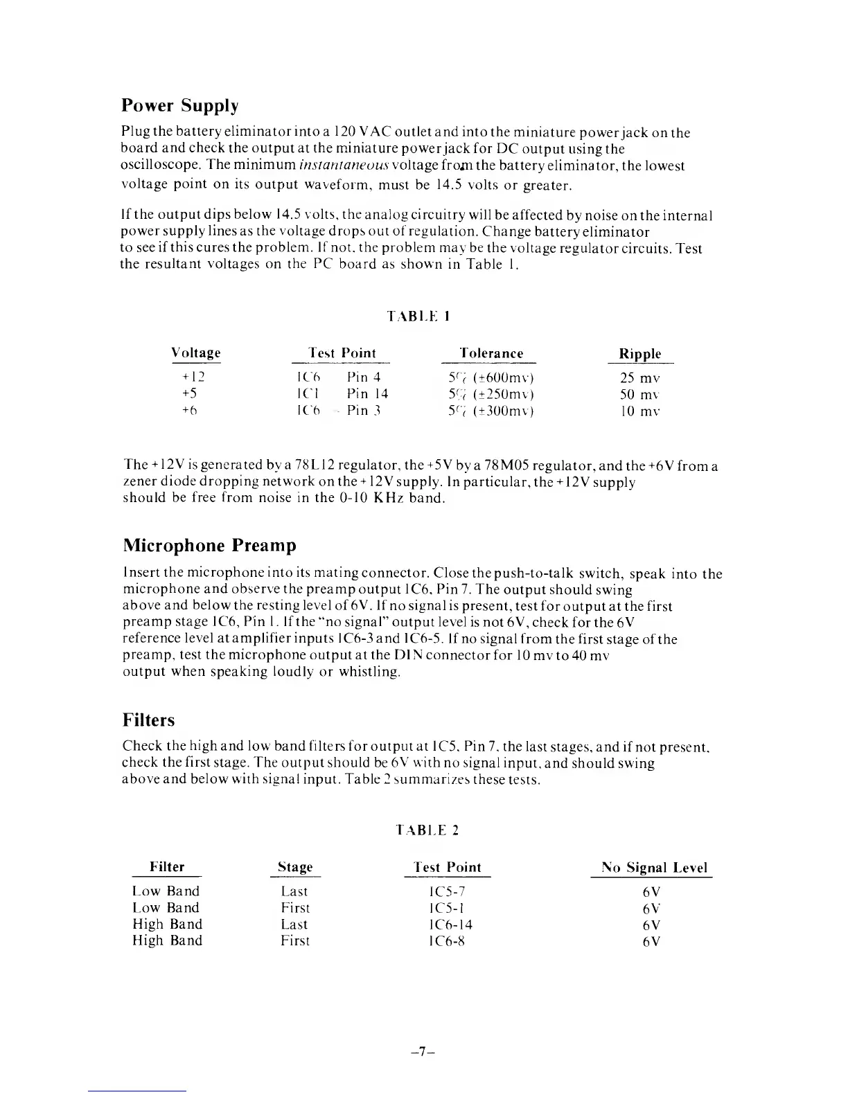
circuits. Test
the
resultant voltages
on
the PC
board as shown
in Table
1.
Voltage
TABLE
Test Point
IC6
Pin 4
1C1
Pin
14
IC6
Pin
3
1
Tolerance
59
(+600mv)
59
(
+
250mv)
5^
(±300mv)
Ripple
+
12
+5
+
6
25 mv
50
mv
10 mv
The
+12V
is generated
by a 78 L
12
regulator, the+5V
by a 78M05 regulator,
and the +6 V
from
a
zener diode dropping network
on the
+
12V supply.
In particular,
the
+
12V
supply
should
be free from
noise in the
0-10
KHz band.
Microphone
Preamp
Insert the microphone into
its mating
connector. Close the
push-to-talk
switch,
speak into
the
microphone and
observe the preamp
output IC6, Pin
7. The
output should
swing
above and below the resting
level of
6V.
If
no
signal
is present,
test for
output at the first
preamp stage IC6, Pin
1. If the "no signal"
output level is not 6V,
check
for the
6V
reference level at amplifier inputs
IC6-3and IC6-5.
If no signal
from the first
stage of the
preamp,
test the microphone
output at the DIN connector
for
10mvto40mv
output when speaking loudly
or whistling.
Filters
Check
the high
and low band filters
for output at IC5. Pin
7. the last
stages, and if
not present,
check the first
stage. The output should
be 6
V
with
no signal input,
and should
swing
above and below with signal
input. Table 2 summarizes
these
tests.
TABLE
2
Filter
Stage
Last
Test
Point
1C5-7
No Signal
Level
Low Band
6V
Low Band First
IC5-1
6V
High Band
Last
1C6-14
6V
High Band
First
IC6-8
6V
 Loading...