ER8G Receiver User Manual
1
Recommended: ELRS Lua Calibration: Telemetry Calibration: Sensors Bind
1 5 5
2
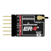
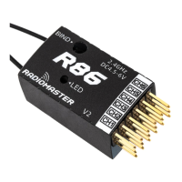
CH1 : C H1
CH2 : C H2
CH3 : C H3
CH4 : C H4
CH5 : C H9
CH6 : C H6
CH7 : C H7
CH8 : C H8
BOOT
DC3.5-8.4V
TX
RX
Expres sLRS 2.4
CH3
CH4
CH1
CH2
CH5
CH6
CH8
CH7
BATT
EXT-V
ANTENNA
EXT-v
60mm
TOP
FRONT
BACK
SIDE
+
RXTX
-
boot
13mm
13.5mm
Battery
3.5-8.4V
TX & RX WIFI INFO
WIFI Network : ExpressLRS TX
WIFI Password: expresslrs
URL: http://10.0.0.1/ (Open in browser)
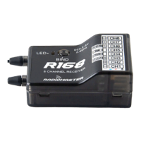
CH6
CH7
CH8
CH3
CH4
CH5
CH1
CH2
BATT
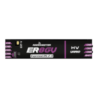
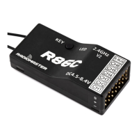
The Radiomaster ER8GV rece ive r has been specially designed for glider
pi lots who require a compact and slim recei ver with a built in vario function.
It can drive up to 8 servos and has buil t-in receiver voltage telemetry and
flight battery telemetry with the ability to automatically detect which voltage
input to use. The ER8GV features a dual-antenna with telemetry power up
to 100mw. The ER8GV can
work with a 1S Lipo receiver batteries.
2. The maximum input voltage for the EXT-V (external voltage input) telemetry
reading is 35V. Do not exceed 35V or the receiver will be damaged.3:
The voltage acquisition of the external battery is connected to the positive pole
of the battery (welded to the positive pole of the ESC). Please be sure to confirm
that the external voltage canno
t be connected separately without connecting
to the BEC.
3. The EXT-V of the ER8GV is accessed via the EXT-V solder pad on the PCB.
A single wire must be soldered to this pad and connected to the positive wire
of the battery or ESC. If no EXT-V power source is found, the ER8GV will default
to reading the voltage on the receiver pins, only one voltage input can be used
at the any
given time.
4. Calibration of the telemetry voltage will be required on your radio. Navigate
to the TELEMETRY page on your radio and locate the RxBt sensor. Edit the
SENSOR settings and adjust the offset until the displayed reading matches
the actual voltage of the battery in the model. If there is a large difference,
adjustment of the ratio may also be required.
5: Channel 6 o
n the receiver must not be used as the power input channel and may
out be used as a servo output channel. Power from an ESC or Receiver battery
must only be applied on Channels 1 to 5. *For best results calibrate the voltage
of your radio using a ful ly charged battery of the correct cell count intended for
use in the model.
6. ExpressLRS Arming requirements and the use of Channel 5:
CH5 is required by
ExpressLRS to set the Arm state of the RF module in your radio. It is recommended
to assign CH5 to a switch such as your throttle cut switch as this will provide benefits
such as dynamic power. Using the ExpressLRS LUA or the Wifi WebUI, you can
assign different channels to the CH5 output of your receiver. See example to the
right: Please visit https://www.e
xpresslrs.org/ to learn more on the importance of
setting up arming.
SPECIFICATIONS
•Size: 60*13.5*13mm
•Weight: 12g
•Power Supply: DC 3.5 - 8.4V
•Antenna Type: 20cm (High Sensitivity Antenna)
•Wireless Protocol: ExpressLRS 3.3.0 (pre-installed)
•Output Channel: 8CH PWM
•Telemetry Power: max. 100mw (LUA Adjustable)
•Built-in high-precision air pressure sensor (Vario)
•External Battery voltage detection range: DC 4.0 - 35V
FIRMWARE
Device Category: Radiomaster 2.4Ghz | Device: RadioMaster ER8G/ER8GV 2400 PWM RX
PASSPHRASE BINDING
1. OPEN the ExpressLRS LUA and navigate to the Wifi Connectivity page. Select the
Enable WIFI option and connect to your radios wifi with a mobile phone, tablet or PC
(See TX WIFI info above). OPEN the ExpressLRS web pa
ge at (http:/ /10.0.0.1/)
and choose a unique bind phrase. Save and Reboot.
2. Power ON the receiver and wait 60 seconds for the LED to blink rapidly to indicate
WIFI mode. Connect your phone, tablet or PC to the receivers WIFI (See RX WIFI
info above). OPEN the ExpressLRS web page at (http://10.0.0.1/) and enter the
matching bind phrase previously entered on your radio. Save and Reb
oot. Once both
radio and receiver have the same bind phrase set they will automatically bind.
TRADITIONAL BINDING
1. The first time you power on your receiver, the LED is doing a quick double blink,
which indicates the receiver is in bind mode. If this is not the case, hold down the boot
button for 10 seconds to reset the receiver.
2. Power ON your transmitter/radio and use the [BIND] but
ton on the ExpressLRS Lua
script, which sends out a binding pulse.
3. If the receiver has a sol id light, it's bound!
*Note: To bind receiver a second time or to another radio, power cycle the
receiver 3 times. On the third power cycle, the LED will double blink indicating
bind mode. If you cannot successfully enter bind mode with the 3 power c
ycle
method, you can hold down the boot button for 10 seconds to reset the receiver to
bind mode or use the passphrase method. WARNING: All previous settings in the
receiver will be erased and need to be re-entered when using the reset button.
SET-UP
1. The recommended ELRS LUA settings on the remote-control end are:
Standard servos:
Packet Rate 100Hz Full
Telem Ratio Std (1:32)ʢ default
ʣ
Switch Mode 8ch
Performance servos:
Packet Rate 333Hz Full
Telem Ratio Std (1:128)
Switch Mode 8ch
IMPORTANT
(*Note: Bind phrases are not secret and can be read.)
(20cm length)
12
GRAMS
2.4
GHZ
Expres sLRS 2.4