F1
F2
English
8005 Rotor Operation Guide
Full/Part Circle Operation (Refer to Figure 1 on fold-out page)
All 8005 rotors are factory preset to part-circle at approximately 180 degrees.
Full-Circle Operation
Insert a flat blade screwdriver into the center adjustment slot on the top of the rotor. Turn the screwdriver clockwise so the blade
is aimed toward the full-circle icon.
Part-Circle Operation
Insert a flat blade screwdriver into the center adjustment slot on the top of the rotor. Turn the screwdriver counter clockwise so
the blade is aimed toward the part-circle icon. Use the following instructions to adjust the arc settings.
Setting the arc - Method #1:
1. Adjust both arc edges of the rotor larger than desired.
2. To adjust the left arc edge, trip the rotor so that it is rotating counter clockwise.
3. Grip the nozzle housing to halt the rotation at the desired trip point.
4. With the rotor aimed at the desired trip point, slowly turn the left adjustment screw in the clockwise direction until the torque of
the nozzle turret is eliminated. This is a very subtle feel. The click sound of the trip may also be heard.
5. Verify trip point during normal operation.
6. Repeat the procedure for the right side trip. The rotor must be tripped to rotate clockwise and the right edge adjustment screw
should be turned counter clockwise to reduce the arc until it trips.
Arc Adjustment
Important facts:
• The rotor may be adjusted to any arc between 50°–330° and full circle.
• Both right and left edges of the arc can be independently adjusted.
• One full 360 degree turn of the arc adjustment screw will change the arc edge approximately 120 degrees. Three full turns
of the arc adjustment screw will rotate the trip edge completely around to the starting point. This is significantly different than
most other rotors.
• The edges of the arc cannot be felt when rotating the nozzle turret by hand. There is a light click sound at the arc edge. If the
nozzle turret is rotated past the trip point, another click may be heard. This is the Memory Arc
®
function activating. No damage
has occurred to the rotor. The rotor will click once again as it is turned back into the area between the arc edges.
• The nozzle turret can be rotated by hand at any time in either direction with no damage to the rotor. The nozzle housing may be
rapid advanced by hand to speed the arc setting process.
• The arc of the rotor cannot be set to less than 50 degrees. If the 50-degree minimum is reached during adjustment, a hard
stop will be felt on the adjustment screw. To continue moving the arc edge, move the other edge in the same direction first.
Then return and continue moving the first edge. If the adjustment screw is forced beyond the fixed stop, it will ratchet and click
loudly a few times before damage occurs.
Setting the arc - Method #2:
1. Determine where the edges of the arc are by rotating the nozzle turret by hand and listening for the click sound or observe the
trip during operation of the rotor.
2. Use the arc adjustment screws to increase or decrease the arc until the trip is at the desired location.
Nozzle Installation (Refer to Figure 2 on fold-out page)
1. Insert the Pull-up Tool into the socket in the top of the rotor and twist 90 degrees. Pull the riser up to gain access to the nozzle
opening and use the hold up tool to support the riser in this extended position.
2. Loosen the nozzle retention screw until it no longer obstructs the nozzle opening in the nozzle housing.
3. Using both thumbs, press the color-coded nozzle firmly into the opening until it is flush with the
nozzle turret.
4. Tighten the nozzle retention screw. The screw threads must engage the front surface of the nozzle to ensure proper seating of
the nozzle.
5. To remove the nozzle, loosen the nozzle retention screw and insert a flat-bladed screwdriver into the Side Pry™ feature on the
lower right edge of the nozzle to pry it loose.
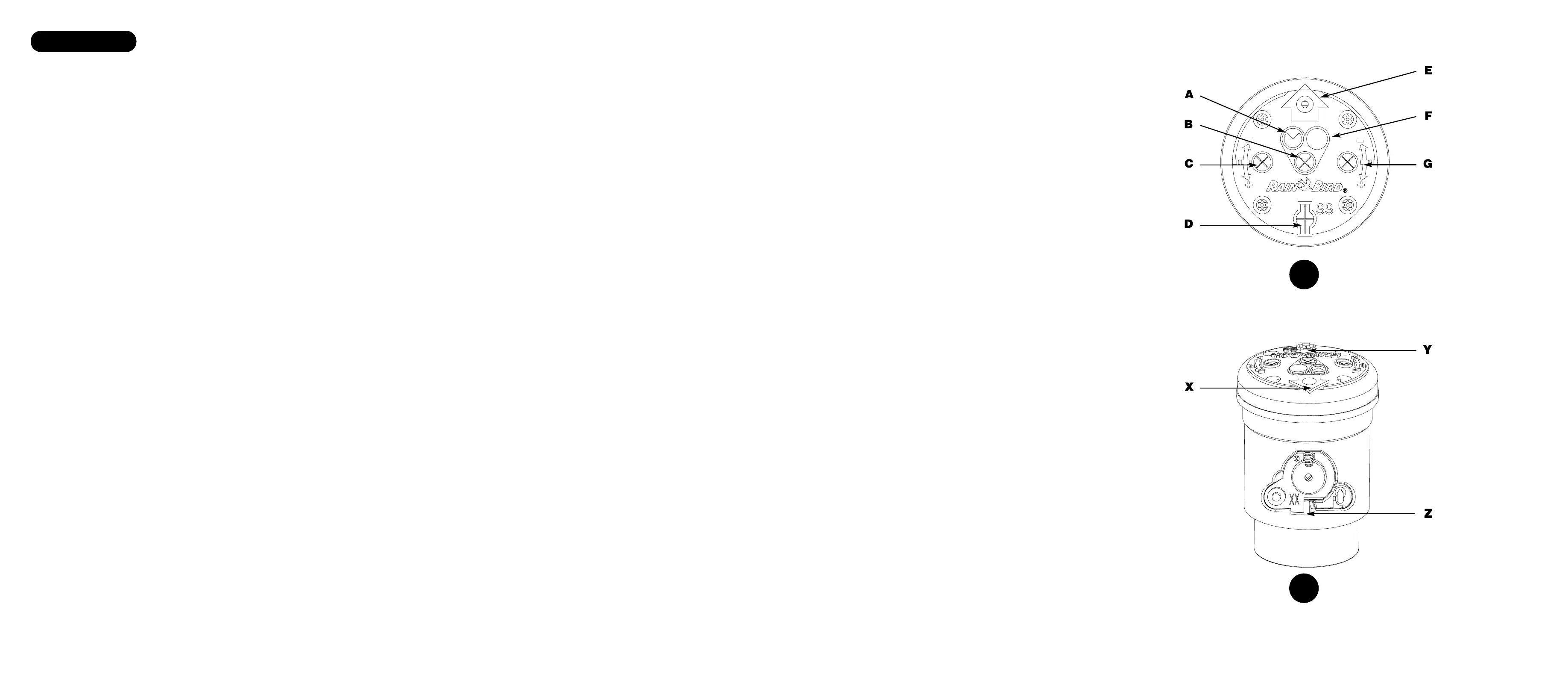
Figure 1 Key
A = Part Circle Icon
B = Full/Part Circle Adjustment Slot
C = Left Edge Arc Adjustment Slot
D = Pull-up Tool Slot
E = Nozzle Retention Screw
F = Full Circle Icon
G = Right Edge Arc Adjustment Slot
Figure 2 Key
X = Nozzle Retention Screw Slot
Y = Pull-up Tool Slot
Z = Side Pry™ Slot
 Loading...