Page 12 of 25
Chapter 5 Status Indicators
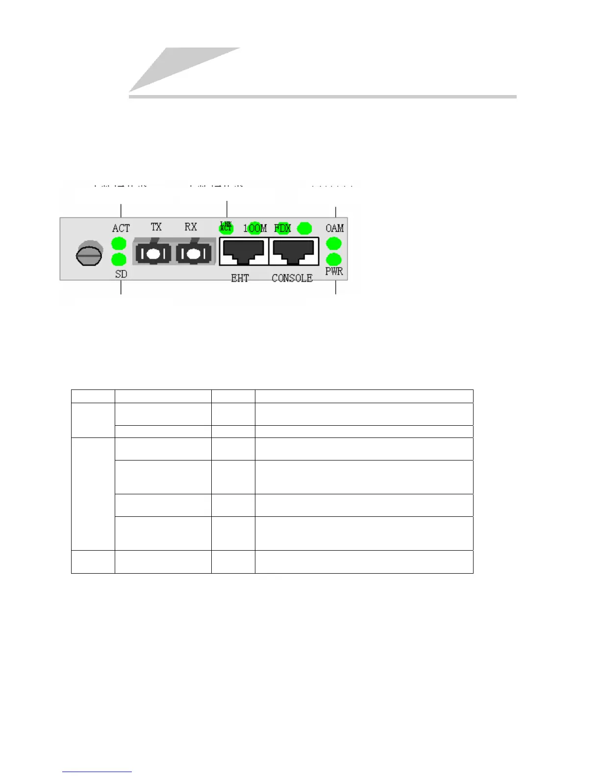
4.1 The Front Panel of RC552-FE(A)
The sketch of front panel of RC552-FE(A):
Electrical Signal ActionOptical Signal Action
Power Supply
Remote Equipment
Optical Signal Detection
4.2 The Indicators of RC552-FE(A)
RC552-FE(A) module’s indicators and their indications are as follows.
Port Name Indicator Explanation
Optical receiving signal
detection
SD
ON: optical signal is detected at receiving link;
OFF: receiving link failure
Fiber
Optical receiving action ACK FLASHING: optical signals are transmitted/received
Remote equipment OAM
ON: remote OAM capable equipment is detected;
OFF: no remote OAM capable equipment is detected.
Copper link/signal action LNK/ACT
ON: copper link is normal;
OFF: copper link failure;
FLASHING: electrical signals are transmiited/received
Copper link speed 100M
ON: copper link speed is 100M;
OFF: copper link speed is 10M.
Copper
Duplex mode/collision FDX
ON: copper link is in full duplex mode;
OFF: copper link is in half duplex mode;
FLASHING: collision is detected at half duplex mode.
Power Power supply PWR
ON: power supply is normal;
OFF: power supply failure.
4.3 The Indicators of 16-slot Chassis
The 16-slot chassis’ indicators and their indications are as follows.
PWR indicator: ON, power supply of chassis is normal.
PS1-5V indicator: OFF, Power Supply 1 is normal, otherwise failure.
PS2-5V indicator: OFF, Power Supply 2 is normal, otherwise failure.