2.4 Pin Definition
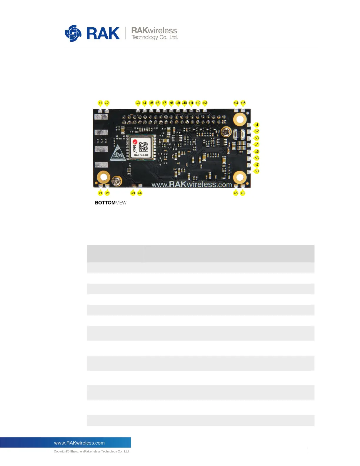
The pins of the RAK2245 shown as following figure.
Figure 3 | RAK2245 Pin Definition
The RAK2245 provides PINs at the bottom side. The description of the pins is given by
the below table.
Supply Voltage for Level Translator
It should be connected to Main Board's UART_RXD. This
pin is connected to GPS Module's UART_TXD internally.
It should be connected to Main Board's SPI_MOSI. And this
pin has been connected to SX1301's SPI_MOSI internally.
It should be connected to Main Board's SPI_CS. And this
pin has been connected to SX1301's SPI_CS internally.
It should be connected to Main Board's SPI_MISO. And this
pin has been connected to SX1301's SPI_MISO internally.
It should be connected to Main Board's SPI_CLK. And this
pin has been connected to SX1301's SPI_CLK internally.
It should be connected to Main Board's UART_TXD. This
pin is connected to GPS Module's UART_RXD internally.