– 4 –
See Chapter 8 in the Users' Guide for more information on
surround sound.
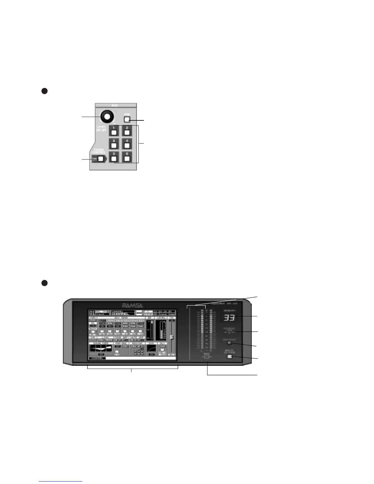
Pressing the bottom knob displays the [DYNAMICS] window
group on the LCD screen.
For more information on the DYNAMICS/DELAY section of
the Top Panel, see Chapter 9 in the Users' Guide.
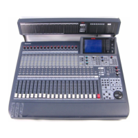
AUX Section
AUX Section
This section of the Top Panel contains controls for routing
selected channels from/to outboard sources. These six aux
routes are independent of the channel input connecters on
the Rear Panel of the
DA7
and greatly expand the flexibility
of the mixer. They can be used as six mono sends, or in
stereo pairs (such as 1&2, 3&4, 5&6), and six mono returns
or stereo pairs. There are two digital aux routes, AUX 1/2,
and four analog aux routes, AUX 3/4 and AUX 5/6. These
are paired for convenience on the Rear Panel connectors. If
you wish to use them as Mono channels, connect a standard
audio “Y” cable (available at your dealer) to split the audio
channels.
Display Bridge
With a channel selected, press an AUX 1-6 LED button
(green) to select which aux route you wish to assign for the
channel. The LEVEL knob performs two functions. By
pressing the knob, you will assign the channel to the
selected aux route, and by turning the knob, you can adjust
the individual channel output to the aux selection. The LED
field of the Channel Fader Strips will reflect the aux
assignments for the channels.
Aux routing is defaulted to a post-fader condition for the
selected channel. Press the PRE LED button to select it
(
red
) and change the aux routing function to a pre-fader
condition.
Press the FADER CONTROL LED button to select it (red)
and display the [FADER CONTROL] window group on the
LCD screen. The window displayed will be determined by
the current AUX 1-6 LED button selection. The channel
fader status of the 32 input channels for the aux selected will
be reflected in the [FADER CONTROL] window, and the
Channel Faders will reset to their respective level positions
for the aux selected.
The AUX/BUS designations at the bottom of the Channel
Fader Strips identify the strip functions when the Fader
Layer AUX/BUS LED button is pressed.
For more information on the AUX section of the Top Panel
see Chapter 10 in the Users' Guide.