– 14 –
Option Card Slots
There are three slots for the optional audio Input/Output
cards, plus one dedicated slot for the SMPTE/V SYNC card.
The space for the SMPTE/V SYNC card is located directly
under the MASTER OUT XLR connectors. Audio option
cards are next to the power switch. The audio option cards
can be used in any of the audio slots, but for TANDEM
operation, the TANDEM card MUST be used in Slot 3.
Video Sync Input [V SYNC]
This is used to connect a vertical synchronizing signal from
a video device.
See Chapter 17, Options in the Users' Guide for more
about SMPTE/V SYNC.
Digital I/O Slot 1 [CH17-24/SLOT 1]
When an option card is inserted into Slot 1, the output of the
connected device appears on Channel Faders 17 through
24, and is controlled by the Fader Layer Inputs 17-32.
Digital I/O Slot 2 [CH25-32/SLOT 2]
When an option card is inserted into Slot 2, the output of the
connected device appears on Channel Faders 25 through
32, and is controlled by the Fader Layer Inputs 17-32.
Digital I/O Slot 3 [CH9-16/SLOT 3]
When an option card is inserted into Slot 3, the output of the
connected device appears on Channel Faders 9 through
16, and is controlled by the Fader Layer Inputs 1-16. This
connection REPLACES the analog inputs 1-16 with
whatever is connected to the option card in Slot 3.
For more information regarding optional slots, see Chapter
12, D-I/O and Chapter 17, Options in the Users' Guide.
Option Card Slots
SELF CHECK FUNCTION
8
The Self Check Function is incorporated in the Digital
Audio Mixer WR-DA7.
1. Test Equipment Required
8
The following Test Jigs are required for Self Check and
Service of the WR-DA7.
8
AD EXTD-1 (Part Number : YWA0EA1196AN) between
the Power-2 Board and AD/DA Board as shown in fig. 1-1.
Fig. 1-1
8
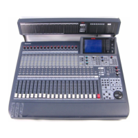
SLOT EXTD (Part Number : YWA0EA1198AN) for the
optional Board as shown in fig. 1-2.
Fig. 1-2
8
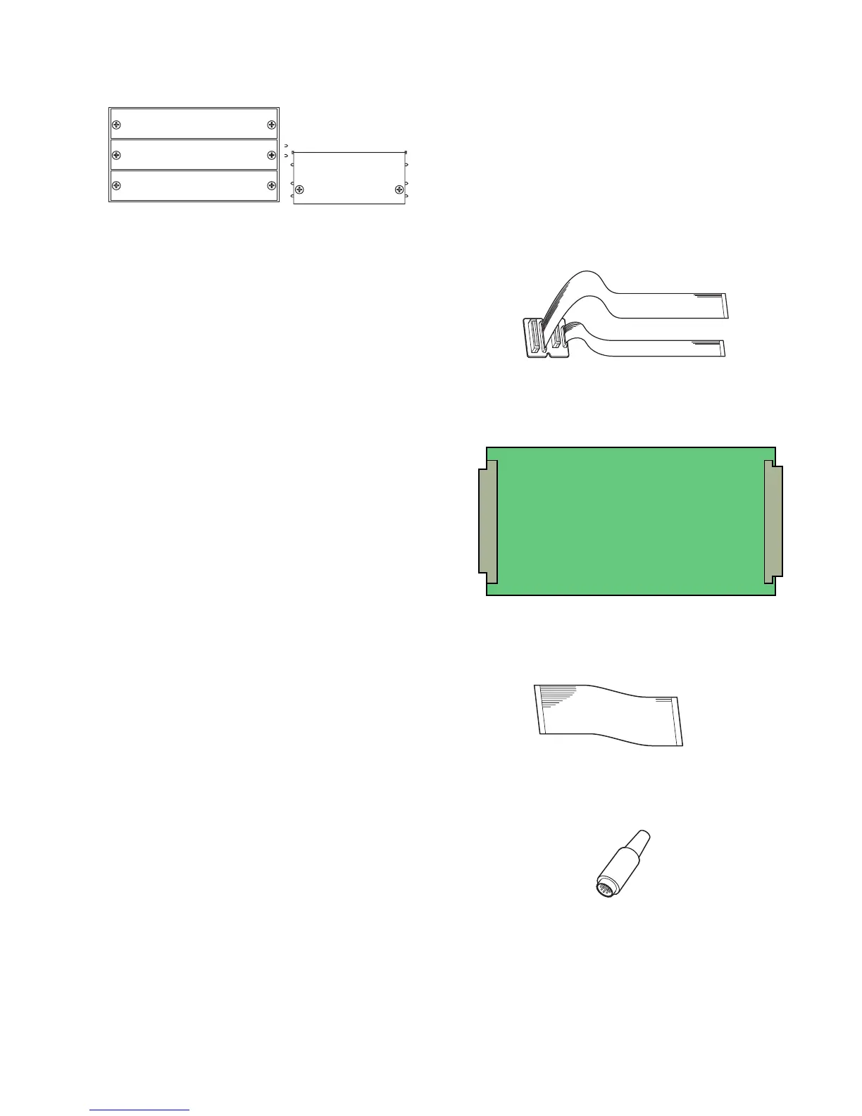
AD EXTD-2 (Part Number : YWA0EA1199AN) between
the Main Board and AD/DA Board as shown in fig. 1-3.
Fig. 1-3
8
PC RTN (Part Number : YWA0EA1200AN) for the PC
Connector as shown in fig. 1-4.
Fig. 1-4