GENERAL
Power Capacity Ratings
Loudspeaker Limitations and Failure Modes
Because there are no 'standard' musical programs with which
to test the power capacity of a loudspeaker, laboratory rating
methods have been
developed.
The purpose of power capacity
ratings is two-fold: to provide a
repeatable,
Industry-standard
basis for comparisons, and to achieve a rating method that
is representative of actual-use conditions. Standard test
signals are repeatable, and provide for reliable comparative
measurements, but test signal evolved to simulate 'typical'
audio programs cannot emulate typical audio programs or
conditions of use by definition. Power capacity ratings are
not absolute, when the program material is other than the
test signal used for the rating. Knowledge of the power
capacity rating method and of practical loudspeaker limitations
can prevent unforeseen failures, rewarding the informed with
years of trouble-free product use.
The power rating method used for the
WS^A500
and WS-A550
is as prescribed by
EIA
(Electronic Industries Association)
RS-426-A (1980). The test signal is shaped random noise,
with a 4:1 (6 dB) peak to average content. The test signal
concentrates most of the energy in the middle frequencies,
while attenuating the lows and highs. The combination of the
filter characteristic and that of white noise — the spectral
energy of the test signal — is what needs to be in Figure 1.
0
-5
10
-15
20
25
in
2
20 Hz
3 4 5 67891
2 3
200 Hz
4 5 67891
Frequency
2
2 kHz
3 4
5
67891 2
20 kHz
Spectral Energy of Gaussian Noise, Shaped by
Electronics Industries Association (EIA) RS-426A (1980)
Filter Characteristic
(Fig.
1)
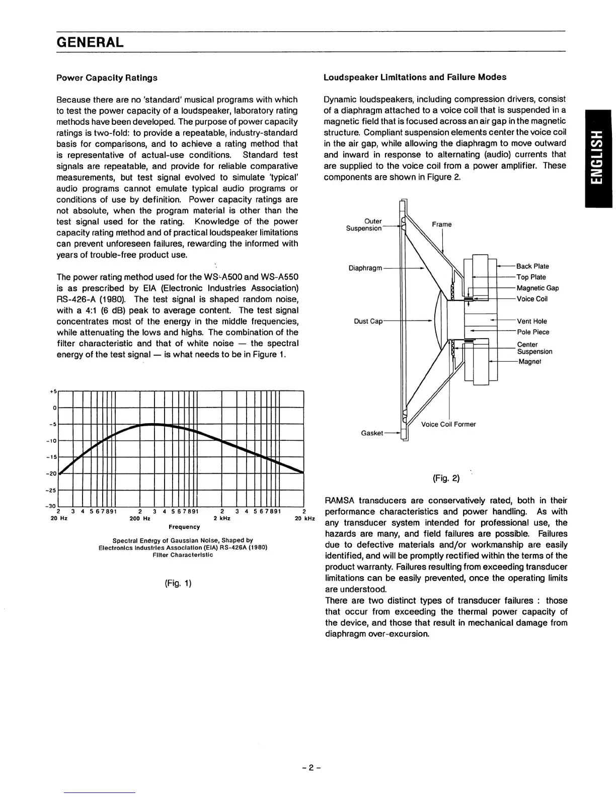
Dynamic loudspeakers, including compression drivers, consist
of a diaphragm attached to a voice
coll
that is suspended in a
magnetic
field
that
is
focused across an air gap
in
the magnetic
structure. Compliant suspension elements center the voice coil
in the air gap, while allowing the diaphragm to move outward
and inward in response to alternating (audio) currents that
are supplied to the voice coil from a power amplifier. These
components are shown in Figure 2.
Outer
Suspension
Diaphragm
Dust Cap
Frame
Back Plate
Top Plate
Magnetic Gap
Voice Coil
Vent Hole
Pole Piece
Center
Suspension
Magnet
Voice Coil Former
Gasket
(Fig.
2)
RAMSA transducers are conservatively rated, both in their
performance characteristics and power handling. As with
any transducer system intended for professional use, the
hazards are many, and field failures are possible. Failures
due to defective materials and/or workmanship are easily
identified,
and will be promptly rectified within the terms of the
product warranty. Failures resulting from exceeding transducer
limitations can be easily prevented, once the operating limits
are understood.
There are two distinct types of transducer failures : those
that occur from exceeding the thermal power capacity of
the device, and those that result in mechanical damage from
diaphragm over-excursion.
 Loading...