The WS-SP2A has balanced instrumentation type
input amplifiers, with excellent common-mode rejection
characteristics. The internal gains have been carefully
structured to preserve operating headroom throughout,
with
a maximum input level of +20 dBv. A 3-5 second delayed
turn-on,
instant-off feature allows the circuitry in the WS-SP2A
to stabilize after energizing, before the outputs are connected.
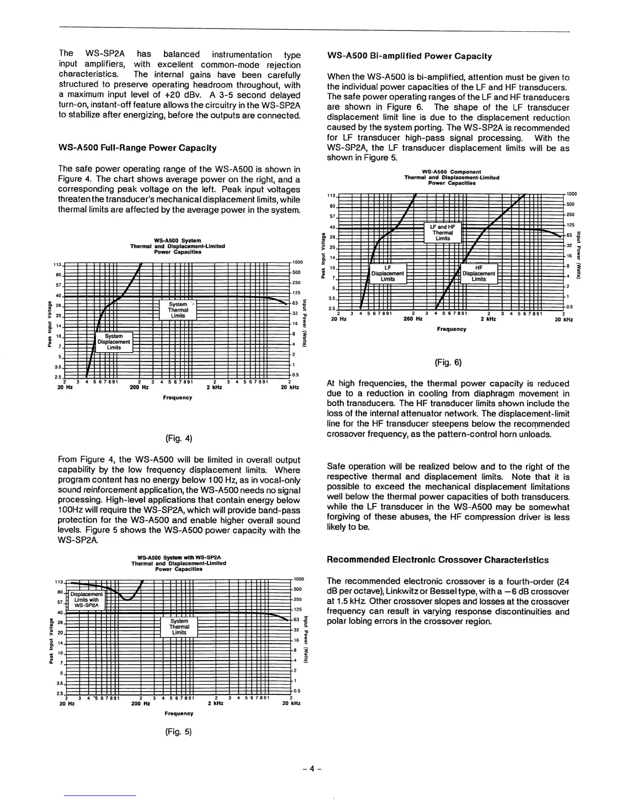
WS-A500 Full-Range Power Capacity
The safe power operating range of the WS-A500
Is
shown in
Figure 4. The chart shows average power on the right, and a
corresponding peak voltage on the left. Peak Input voltages
threaten the transducer's mechanical displacement
limits,
while
thermal limits are affected by the average power in the system.
WS-A500
System
Thermal and Displacement-Limited
Power Capacities
System
Thermal
Limits
System
Displacement
f
Limits
5 6
7
891
5 6
7
891
Frequency
(Fig.
4)
WS-A500
Bi-amplified
Power Capacity
When the WS-A500 Is
bi-amplified,
attention must be given to
the individual power capacities of the LF and HF transducers.
The safe power operating ranges of the LF and
HF
transducers
are shown in Figure 6. The shape of the LF transducer
displacement limit line is due to the displacement reduction
caused by the system porting. The WS-SP2A is recommended
for LF transducer high-pass signal processing. With the
WS-SP2A, the LF transducer displacement limits will be as
shown in Figure 5.
WS-ASOO Component
Thermal and Displacement-Limited
Power Capacities
LFandHF
Thermal
Limits
HF
Displacement
Limits
Displacement
4 5 6
7 891
5 6
7
891
5 6
7
891
2 kHz
Frequency
(Fig.
6)
At high frequencies, the thermal power capacity is reduced
due to a reduction in cooling from diaphragm movement in
both transducers. The HF transducer limits shown include the
loss of the
Internal
attenuator network. The displacement-limit
line for the HF transducer steepens below the recommended
crossover frequency, as the pattern-control horn unloads.
From Figure
4,
the WS-A500 will be limited in overall output
capability by the low frequency displacement limits. Where
program content has no energy below
100
Hz,
as in vocal-only
sound reinforcement
application,
the WS-A500 needs no signal
processing. High-level applications that contain energy below
100Hz
will require the
WS-SP2A,
which will provide band-pass
protection for the WS-A500 and enable higher overall sound
levels. Figure 5 shows the WS-A500 power capacity with the
WS-SP2A
Safe operation will be realized below and to the right of the
respective thermal and displacement limits. Note that it is
possible to exceed the mechanical displacement limitations
well below the thermal power capacities of both
transducers,
while the LF transducer in the WS-A500 may be somewhat
forgiving of these abuses, the HF compression driver is less
likely to be.
WS-ASOO
System
with WS-SP2A
Thermal and Displacement-Limited
Power Capacities
Displacement
Limits
with
WS-SP2A
System
Thermal
Limits
5 6
7 8
Recommended Electronic Crossover Characteristics
The recommended electronic crossover is a fourth-order (24
dB per
octave),
Linkwitz or Bessel
type,
with a
—6
dB crossover
at
1.5
kHz. Other crossover slopes and losses at the crossover
frequency can result in varying response discontinuities and
polar lobing errors in the crossover region.
Frequency
(Fig.
5)
-4-
 Loading...