Subwoofer Arrays
Mutual Radiation Effects
Multiple direct radiator systems will behave as a single
loudspeaker, providing the array is of finite dimensions
and all of the component parts vibrate in phase and with
identical velocity amplitudes. Under these conditions, the
volume displacement of the array is the sum of the volume
displacements of the component transducers. Figure 12
dimensions various arrays of WS-A550 modules and Table
A lists the performance characteristics for each array
configuration, from one to sixteen modules.
O
o o
t
1-10
-2-7-
o o
OO
oo
-3-8-
SO
so
OS
OS
t
1-10
2-7
-3-8-
-7-3-
SO
so
so
so
OS
OS
OS
OS
5-3
SO
so
so
so
so
so
so
so
OS
OS
OS
OS
OS
OS
OS
OS
(Fig.
12)
Characteristic
Pressure Sensitivity
(1
w/1
m)
Array Reference
Elliciency
(half space)
Thermal
Power
Capacity (EIA
HS-426-A)
1 m (equivalent) SPL
al
1 dB
Thermal Power Compression
-3 dB Lower
Frequency (hall
space}
Piston Band
Frequency Limit
Volume Displacement
(VD)
VO Equivalent
SPL @ 50 Hz
Power Output, 35 Hz - 50 Hz
(acouslic watts)
Nominal Impedance
(Combinations)
Total Volume
(for transport)
Total Weight (kg)
Quantity of WS-A550 Modules in Array
1
91
dB
0.85 %
400w
113
dB
35
Hz
400 Hz
6.0
x 10
2
cm
3
112
dB
1w
en
2.1
It
3
16
kg
2
94
dB
1.7%
800
w
119
dB
34
Hz
170 Hz
1.2x10
3
cm
3
118
dB
4w
40
2@sn
4.2
ft
3
32 kg
4
97
dB
3.4 %
1.600
w
125
dB
32
Hz
125 Hz
2.4x10
3
cm
3
124
dB
16
w
2£ï.
2@4Q
8.5
ft
3
64 kg
8
100
dB
6.8%
3.200
w
131
dB
30
Hz
75
Hz
4.8
x
10
3
cm
3
130
dB
64
w
2@2U,
4@4tl
17
ft
3
128
kg
16
103
dB
13.6%
6.400
w
137
dB
28
Hz
50 Hz
9.6
x
10
3
cm
3
136
dB
256
w
4@2£1.
a@4n
34
It
3
256
kg
These performance characteristics are only valid for coherent
arrays, that is, arrays within which all of the radiating
transducers can be circumscribed by the shortest wavelength
of coherent summation. This is the indicated upper frequency
listed in Table A. As the array gets larger, the upper frequency
limits move downward.
Boundary Conditions
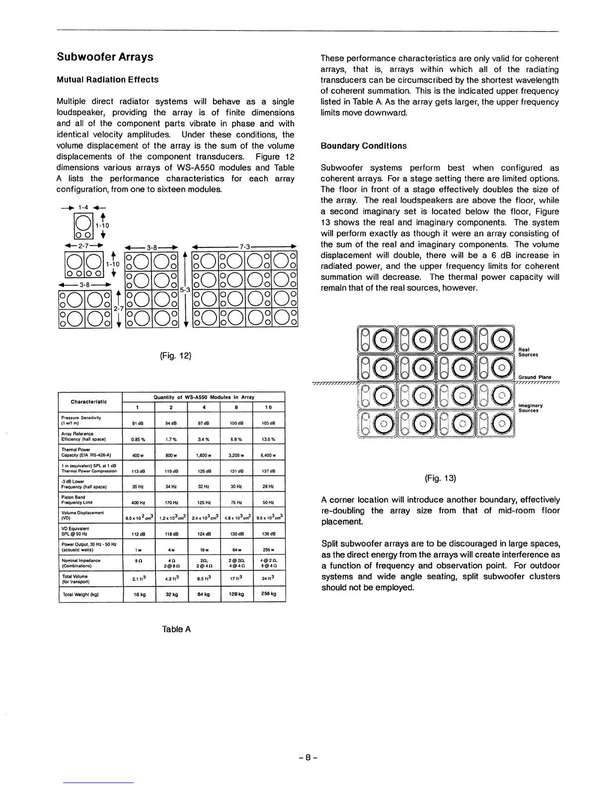
Subwoofer systems perform best when configured as
coherent arrays. For a stage setting there are limited options.
The floor
In
front of a stage effectively doubles the size of
the array. The real loudspeakers are above the floor, while
a second imaginary set is located below the floor, Figure
13 shows the real and imaginary components. The system
will perform exactly as though it were an array consisting of
the sum of the real and imaginary components. The volume
displacement will double, there will be a 6 dB increase in
radiated power, and the upper frequency limits for coherent
summation will decrease. The thermal power capacity will
remain that of the real sources, however.
Ground Plane
Imaginary
Sources
(Fig.
13)
A corner location will introduce another boundary, effectively
re-doubling the array size from that of mid-room floor
placement.
Split subwoofer arrays are to be discouraged in large spaces,
as the direct energy from the arrays will create interference as
a function of frequency and observation point. For outdoor
systems and wide angle seating, split subwoofer clusters
should not be employed.
Table A
-8-
 Loading...