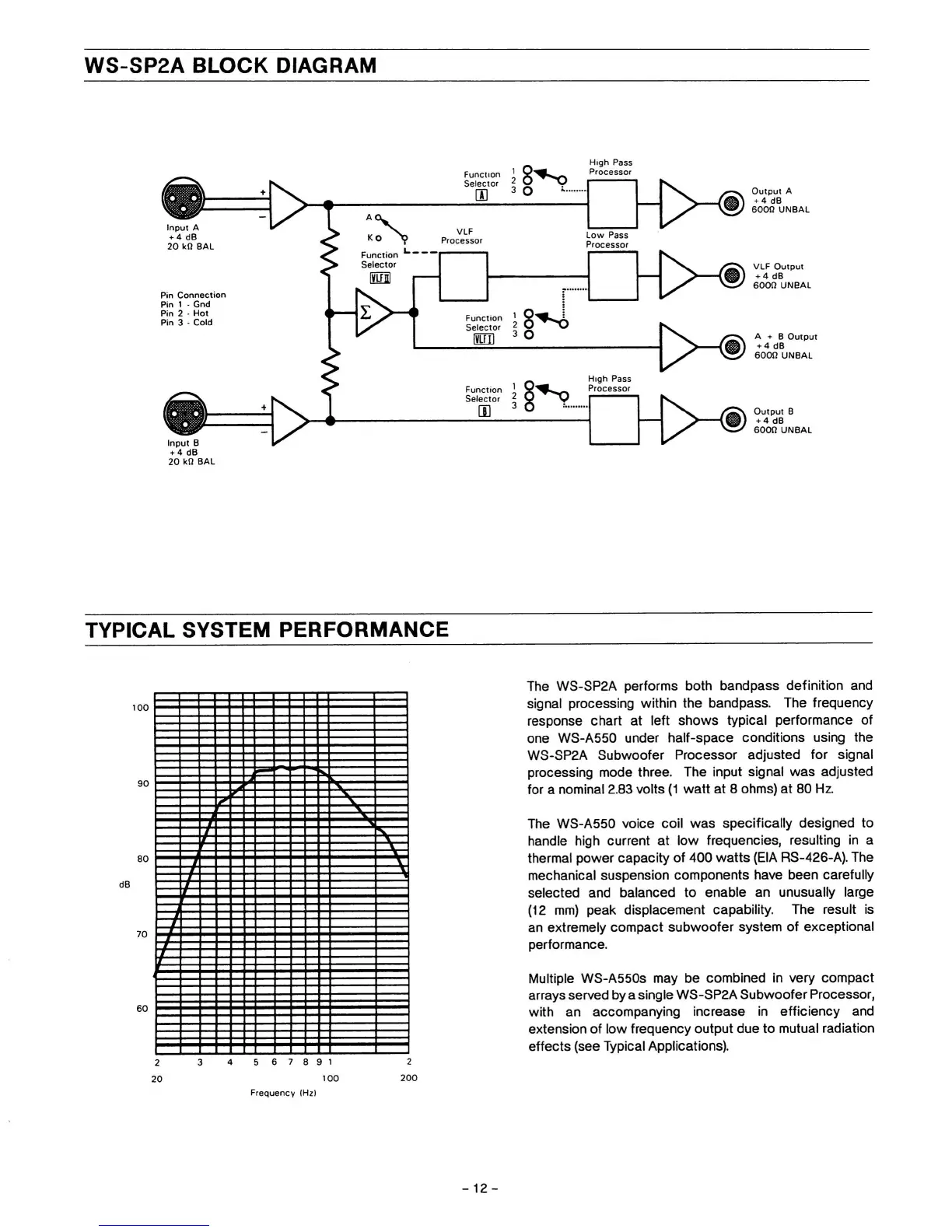
WS-SP2A BLOCK DIAGRAM
Output A
+ 4 dB
600!)
UNBAL
VLF Output
+ 4 dB
600« UNBAL
High
Pass
Processor
Function
Selector
Input
A
VLF
Processor
Low Pass
Processor
20
M SAL
Function
Selector
El
Pin Connection
Pin
1
- Gnd
Pin 2 - Hot
Pin 3 - Cold
Function
Selector
um
A + B Output
MdB
B00ÍI
UNBAL
High
Pass
Processor
Function
Selector
>
Output B
4-4
dB
BOOH UNBAL
Input B
20
k(l
BAL
TYPICAL SYSTEM PERFORMANCE
The WS-SP2A performs both bandpass definition and
signal processing within the bandpass. The frequency
response chart at left shows typical performance of
one WS-A550 under half-space conditions using the
WS-SP2A Subwoofer Processor adjusted for signal
processing mode three. The
input
signal was adjusted
for a nominal 2.83 volts
(1
watt at 8 ohms) at 80 Hz.
The WS-A550 voice coil was specifically designed to
handle high current at low frequencies, resulting in a
thermal power capacity of 400 watts (EIA
RS-426-A).
The
mechanical suspension components have been carefully
selected and balanced to enable an unusually large
(12 mm) peak displacement capability. The result is
an extremely compact subwoofer system of exceptional
performance.
Multiple WS-A550S may be combined in very compact
arrays served by a single WS-SP2A Subwoofer Processor,
with an accompanying increase In efficiency and
extension of low frequency output due to mutual radiation
effects (see Typical Applications).
2 3 4 567891
20
100
Frequency
IHzl
2
200
-12-