Thermal Power Limits
The voice
colls
of RAMSA professional loudspeakers are
designed to operate at very
high
temperatures before risk
of a 'burnout' failure. However, It is useful to remember that
the vast majority of the power in a loudspeaker Is converted to
heat, with only a small percentage of the energy converted into
acoustic power. Because the voice coil is operating in an air
gap,
precious little heat Is conducted away through the cone
and suspension elements. Some of the heat is radiated to the
transducer's metal parts, but the majority of the cooling comes
from air circulation.
The outward and inward movement of the diaphragm creates
air movement to cool the voice
coil,
without which the coil
would be subject to greater heating and premature thermal
failure.
The EIA RS-426A test signal contains sufficient low
frequency information to create air movement across the voice
coil that is typical of program material use conditions, but
the weighting precludes high power at low frequencies that
could
induce
mechanical failures by exceeding transducer
displacement limits. Power ratings based upon the EIA
RS-426A rating method are, therefore, appropriate thermal
power limits for program use conditions.
Both the WS-A500 (operated with its internal passive
crossover) and WS-A550 can easily sustain their (RS-426A)
thermal rated power, but can be damaged by exceeding
mechanical displacement limits (currently, there are no
displacement-limited power capacity rating methods). When
the WS-A500 Is
bi-amplified,
special precautions are
necessary to protect the HF transducer from damage.
Mechanical Power Limits
A loudspeaker imparts sound pressure to the air, alternately
compressing and rarefying by outward and inward diaphragm
movement for each Hz of audio information. (One Hertz is
a complete cycle of diaphragm movement, beginning from rest
position to the outward peak, returning through the rest position
to the inward peak, and finally returning outward to the rest
position.) The rate at which the diaphragm completes cycles is
the frequency, while the energy produced is proportional to the
product of frequency squared and diaphragm displacement.
For constant frequency-energy output
(flat
power response),
direct-radiating diaphragms must quadruple
In
displacement
for each halving of frequency.
All transducers have mechanical diaphragm displacement
limits.
Depending upon the transducer's design, the limits are
reached when the voice coil is driven out of the magnetic
field,
or when the suspension can no longer stretch to
allow diaphragm movement. In the former case, the driving
electromagnetic force diminishes as the voice
coll
begins to
leave the air gap. Under the conditions, it
Is
unlikely that the
transducer would be easily damaged through over-excursion,
as the driving force Is reduced before the suspension limits are
reached.
The LF transducer of the model WS-A500 is of this
type.
With other design approaches, the available voice coil travel
and electromotive strength can be sufficient to exert damaging
forces upon the suspension components. Transducers
intended for extended bass or subwoofer applications
generally feature very long voice coils and high dynamic forces
to enable large volume displacement. With these 'long-throw'
devices, physical damage is possible at electrical power levels
that are less than the thermal power capacity rating of the
speaker, depending upon the
frequency-magnitude
of the audio
signal.
The transducer in the WS-A550 subwoofer system is
typical of a class of devices with these characteristics.
Signal Processing Requirements
The WS-A500 and WS-A550 loudspeaker systems are
capable of high performance in demanding professional-use
application. Both systems are highly-specialized devices, and
have been optimized for operation within specific frequency
ranges. To achieve optimal performance, the WS-A500 and
WS-A550 should be used with the RAMSA model WS-SP2A,
which provides band-pass signal processing for both speaker
systems.
The WS-SP2A installs between the mixer and the power
amplifiers, providing stereo
Inputs,
a summed subwoofer
output, stereo high-passed outputs for two channels of
main loudspeakers and summed (mono) full-range output.
The subwoofer processor provides WS-A550 systems an
electrically-assisted alignment and high-pass protection to
enable operation to a —3 dB frequency of 35 Hz. Three
subwoofer low-pass
frequencies
(50 Hz, 80 Hz and
125
Hz) are
available, along
with
complementary stereo signal processing
the WS-A500.
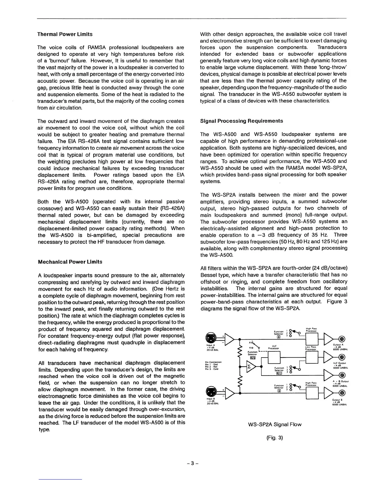
All filters within the WS-SP2A are fourth-order (24 dB/octave)
Bessel type, which have a transfer characteristic that has no
offshoot or ringing, and complete freedom from oscillatory
instabilities. The internal gains are structured for equal
power-instabilities. The internal gains are structured for equal
power-band-pass characteristics at each output. Figure 3
diagrams the signal
flow
of the WS-SP2A.
8^o
i
Processc
Sei
^M§)
Œ
©
X
d
dB
dii
soon
uNBAi
20 Ml BAL
-T>M§)
©
EFJ
>*
Pin Conned
LF Output
Gnd
Pin
2 Hot
6001) UNBAL
Pin 3 - Cold
r>-<§)
fycm
©
B
Outp
4 dB
"^0
Func
6000
UNBAL
Inrjuf
B
<
Selec
V-®
m
©
B
Output B
B
4
dB
20
kit SAL
600(1 UNBAL
WS-SP2A Signal Flow
(Fig.
3)
-3-
 Loading...