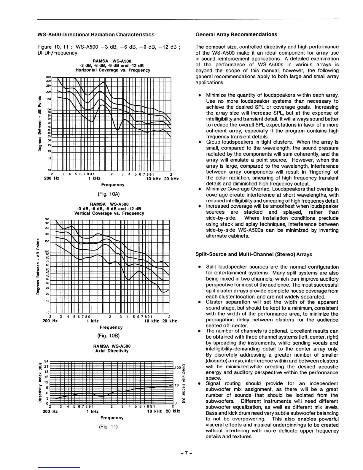
WS-A500 Directional Radiation Characteristics
General Array Recommendations
Figure 10,
11
: WS-A500
DI-DF/Frequency
-3 dB, -6 dB, -9 dB, -12 dB
RAMSA WS-A500
-3 dB, -6 dB, -9 dB and -12 dB
Horizontal Coverage vs. Frequency
360
100
80
70
60
50
46
40
35
30
?5
20
15
10
V---A
\
S»
-
=
">-\
V--
-^
\ /
/r
\,J4
:;-::£
.
s
K
.tz
f
^
-*
\
\
\
:*$::
-/-S--
Z---S.
-,v
._ _..._.
\
2 3
200 Hz
5 6 7 891
1 kHz
5 6 7 891 2
10 kHz 20 kHz
Frequency
(Fig.
10A)
RAMSA WS-A500
-3 dB, -6 dB, -9 dB and -12 dB
Vertical Coverage vs. Frequency
am
?sn
?oo
ISO
100
90
80
70
60
50
4b
40
35
30
25
?0
15
S
\
s,
's,
\
v
<\
—-
v.
,
V
2 3
200 Hz
4 5 6 7 891
1 kHz
4 5 6 7 891 2
10 kHz 20 kHz
Frequency
(Fig.
10B)
RAMSA WS-A500
Axial Directivity
-10
-ID
.0
2 3
200 Hz
5 6 7 891
1 kHz
6 7 8 9
1
10 kHz
2
20 kHz
Frequency
(Fig.
11)
The compact size, controlled directivity and high performance
of the WS-A500 make it an ideal component for array use
in sound reinforcement applications. A detailed examination
of the performance of WS-A500s in various arrays is
beyond the scope of this manual, however, the following
general recommendations apply to both large and small array
applications.
• Minimize the quantity of loudspeakers within each array.
Use no more loudspeaker systems than necessary to
achieve the desired SPL or coverage goals. Increasing
the array size will increase SPL, but at the expense of
intelligibility and transient detail. It will always sound better
to reduce the overall SPL expectations in favor of a more
coherent array, especially if the program contains high
frequency transient details.
• Group loudspeakers in tight clusters. When the array is
small,
compared to the wavelength, the sound pressure
radiated by the components will sum coherently, and the
array will emulate a point source. However, when the
array is large, compared to the wavelength,
Interference
between array components will result in 'fingering' of
the polar radiation, smearing of high frequency transient
details and diminished high frequency output.
• Minimize Coverage Overlap. Loudspeakers that overlap
in
coverage create interference at short wavelengths, with
reduced
intelligibility
and smearing of high
frequency
detail.
• Increased coverage will be smoothest when loudspeaker
sources are stacked and splayed, rather than
side-by-side. Where installation conditions preclude
using stack and splay techniques, interference between
side-by-side WS-A500s can be minimized by inverting
alternate cabinets.
Split-Source and Multi-Channel (Stereo) Arrays
• Split loudspeaker sources are the normal configuration
for entertainment systems. Many split systems are also
being mixed in two channels, which can improve auditory
perspective for most of the audience. The most successful
split cluster arrays provide complete house coverage from
each cluster location, and are not widely separated.
• Cluster separation will set the width of the apparent
sound stage, but should be kept to a minimum, consistent
with the width of the performance area, to minimize the
propagation delay between clusters for the audience
seated off-center.
• The number of channels is optional. Excellent results can
be obtained with three channel systems (left, center, right)
by spreading the instruments, while sending vocals and
intelligibility-demanding detail to the center array only.
By discretely addressing a greater number of smaller
(discrete) arrays, interference within and between clusters
will be
minlmlzed.while
creating the desired acoustic
energy and auditory perspective within the performance
space.
• Signal routing should provide for an independent
subwoofer mix assignment, as there will be a great
number of sounds that should be isolated from the
subwoofers. Different Instruments will need different
subwoofer equalization, as well as different mix levels.
Bass and kick drum need very subtle subwoofer balancing
to not be overpowering. This also enables powerful
visceral effects and musical underpinnings to be created
without interfering with more delicate upper frequency
details and textures.
 Loading...