AM25 •18
Length required = Number of turns x 0.6 nches.
For example: 35 turns required. 35 x 0.6” = 21”
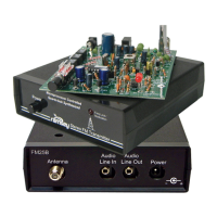
104. Wind the toroid cores, L1, 2 and 3 with the
proper number of turns. One pass through the core
counts as one turn. Leave each end 1/2” long and
tin each end.
105. Install L1, 2 and 3. The inductors stand upright;
there is no need to secure them unless you will be
subjecting you kit to vibration. In that case you can
use a dab of glue to hold each inductor.
106. Referencing the frequency table, Plug the
jumper block over the proper pin numbers on Header block H1.
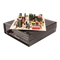
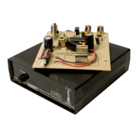
You have just completed your AM25 wireless broadcast transmitter. Take a
well deserved break now. Give your eyes a rest. When you return, be sure to
check over your work on the entire circuit board. Energizing the circuit board
with solder “bridges” or misplaced components can damage your kit.
ANTENNA CONSIDERATIONS
For many applications, a 5 - 6 foot wire antenna connected to the center pin
of the “RF OUT” connector will produce satisfactory results.
Another simple but effective hint is to connect the chassis “ground” to a good
earth ground (like a cold water pipe, etc.). Be sure, however, that the total
length of the antenna, feedline, and grounding wire is less than 10 feet as
required by the FCC Part 15 rules.
Once you check the PC board for any errors and hook-up some sort of
antenna, it’s time to program in your frequency and align your transmitter.
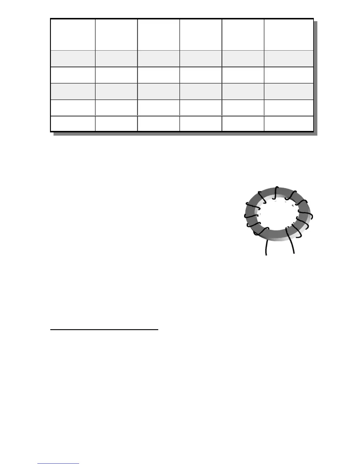
Maximum
Frequency
(KHz)
C3 and C7 L1 and L3
No. of
turns
C4 and C5 L2
No. of
turns
Band Jumper
(H1)
Jumper pins
790 2200 pF 29 8200 pF 31 2 - 3
950 1500 pF 27 6800 pF 28 2 - 3
1150 1000 pF 25 5600 pF 27 1 - 2
1350 470 pF 23 4700 pF 24 1 - 2
1710 none 20 3900 pF 21 1 - 2