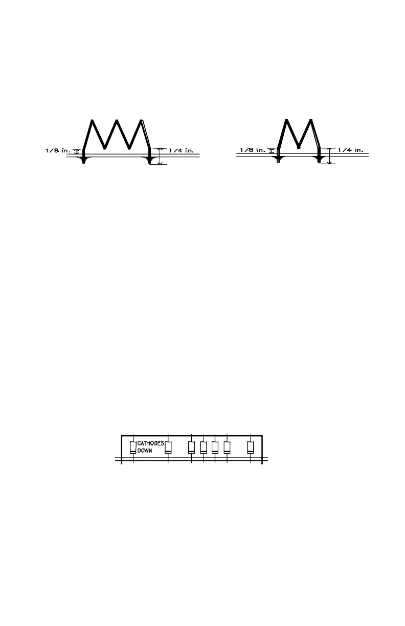
The legs or leads for inserting L12,13,15,16 and L22 should be 1/4"
long. The coil should sit 1/8" maximum above the PC board
groundplane.
Assembly Stage "TO": Programming Standard Repeater Offsets
(- 1.6 and + 1.6 MHz)
If you did not go ahead and do so when setting up the PLL Synthesizer for
receiver testing in Stage "H", now would be a good time to install the diode
programming for the standard transmit offsets. We discuss Auxiliary or Non-
Standard offsets in the Reference section of this book (page 34-36). The
following programming will set up your transceiver for normal 220 MHz band
operation, still leaving the AUX line for programming one non-standard split. If
you have an unusual application requiring more than one non-standard split,
you will have to give up one or more standard + or - 1.6 MHz splits.
TO1. Referring back to Stage "H" as needed, prepare three 3" long diode
bridges for the offset matrix.
TO2. Install these 3 bus wire bridges in the -RPT, +RPT, and AUX lines.
TO3. For - 1.6 MHz TX offset, install 8 diodes in the positions clearly
marked for the -RPT line:
[ ] 8K [ ] 4K [ ] 2K [ ] 1K [ ] 512 [ ] 128 [ ] 64
REMEMBER: position cathode (banded) ends down!
TO4. For + 1.6 MHz TX offset, install 2 diodes in the +RPT line:
[ ] 256 [ ] 64
2.5 TURN
1.5 TURN
 Loading...