11
RAMTECHGLOBAL.COM
Typical Scenarios
WES3 Water Interface
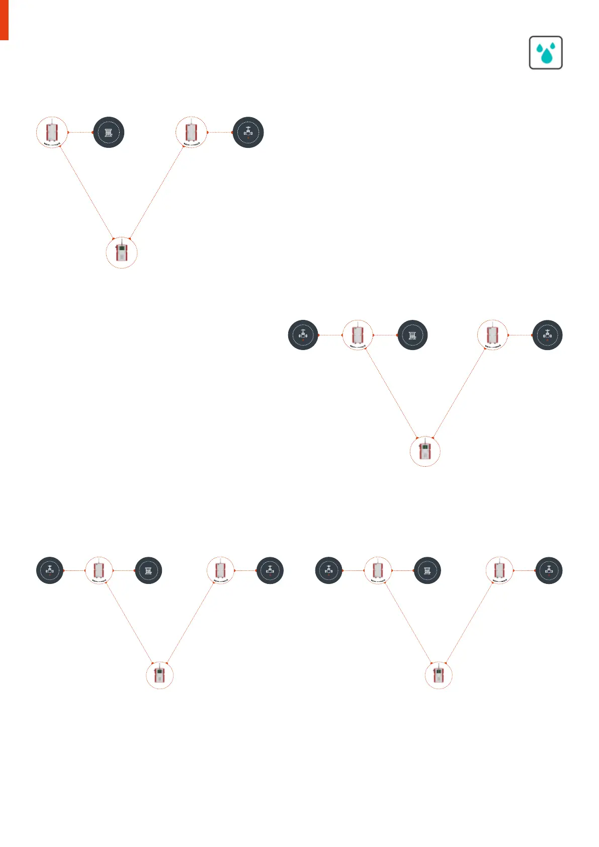
Scenario One
I20 1 has a WES Water Cable Sensor fitted to the input of the device. This is
configured to monitor the pipework in a plant room while refurbishment work
takes place. This is located a couple of hundred metres away from the main
shut-o valve. Nothing is attached to the output.
I20 2 is deployed next to the shut-o valve. Nothing is attached to the input
but the output is connected to the shut-o valve. In this scenario the water
is detected by I20 2 which triggers the input and raises a “WTR” alert on the
WES3 network.
This triggers the output on all Water I20’s (in this instance I20 2 only. This then
shuts o the valve via I20 2. A “WTR” alert is triggered on the WES3 Connect
and (where used) the REACT cloud and mobile application.
W
A
T
E
R
I
N
T
E
R
F
A
C
E
W
A
T
E
R
D
E
T
E
C
T
I
O
N
C
A
B
L
E
C
O
N
N
E
C
T
W
A
T
E
R
I
N
T
E
R
F
A
C
E
V
A
L
V
E
Scenario Two
I20 1 has a WES Water Cable Sensor fitted to the input of the
device. The shut-o valve in this case is co-located within the
plant room so the output from I20 1 is connected directly to this,
i.e. both the input and output are connected.
I20 2 is deployed next to an adjacent shut-o valve. Nothing is
attached to the input, the output is connected to the shut-o
valve. In this scenario the water is detected by I20 1 which triggers
the input and raises a “WTR” alert on the WES3 network.
This triggers the output on all Water I20’s (in this instance I20 2
and also the valve connected to I20 1. Both valves are therefore
shut o. A “WTR” alarm is triggered on the WES3 Connect and
(where used) the REACT cloud and mobile application.
W
A
T
E
R
I
N
T
E
R
F
A
C
E
W
A
T
E
R
D
E
T
E
C
T
I
O
N
C
A
B
L
E
C
O
N
N
E
C
T
W
A
T
E
R
I
N
T
E
R
F
A
C
E
V
A
L
V
E
V
A
L
V
E
W
A
T
E
R
I
N
T
E
R
F
A
C
E
W
A
T
E
R
D
E
T
E
C
T
I
O
N
C
A
B
L
E
C
O
N
N
E
C
T
W
A
T
E
R
I
N
T
E
R
F
A
C
E
V
A
L
V
E
V
A
L
V
E
W
A
T
E
R
I
N
T
E
R
F
A
C
E
W
A
T
E
R
D
E
T
E
C
T
I
O
N
C
A
B
L
E
C
O
N
N
E
C
T
W
A
T
E
R
I
N
T
E
R
F
A
C
E
V
A
L
V
E
V
A
L
V
E
Scenario Three
Two separate zones - I20 1 has a WES Water Cable Sensor fitted to the input of the device. The shut-o valve in this case is co-located within
the plant room so the output from I20 1 is connected to directly to this, i.e. both input and output are connected. I20 2 is deployed next to an
adjacent shut-o valve. Nothing is attached to the input but the output is connected to the shut-o valve.
In this scenario the water is detected by 120 1 which triggers the input and raises a “WTR” alert on the WES3 network. This triggers the output
on all Water I20’s (in this instance I20 2 and also its own valve at 120 1). Both valves are therefore shut o. A “WTR” alarm is triggered at the
WES3 Connect and (where used) the REACT cloud and mobile application.
I2O 1 I2O 2
CONNECT
I2O 1 I2O 2
CONNECT
I2O 1 I2O 2
CONNECT
I2O 1 I2O 2
CONNECT
 Loading...