57
%\SUHVVLQJEXWWRQCWKHIDFWRU\EDUUHJXODWLRQ
is set.
After having regulated the desired pressure, press D
to save the setting and quit the menu.
ATTENTION: during programming, water dispen-
sing is interrupted while heater pressure control is
in use.
10.2. Auto-test components
Electronic card E 06 foresees auto-testing
ZLWK ZKLFKLW LV SRVVLEOH WR YHULI\ RSHUDWLRQRI WKH
electric/electronic components of the machine one
E\RQH
,QRUGHUWRXWLOLVHWKLVIXQFWLRQLWLVQHFHVVDU\WRHQWHU
WKHHOHFWURQLFFDUGE\GLVPDQWOLQJWKHOHIWSDQHORIWKH
machine (a descriptive label of the auto-test function
is attached to the inside of the panel).
7KHVHTXHQFHLVJXLGHGE\PHDQVRIWKHGLVSOD\DW
the centre of the electronic card.
Since the auto-test is carried out on the open
machine, be careful not to touch the parts
under voltage.
To enter the auto-test menu proceed as follows:
- Switch off the machine.
- Keeping push button ARIWKH¿UVWJURXSSUHVVHG
¿JVZLWFKRQWKHPDFKLQH
- Push buttons A, B, C and D¿JOLJKWXSDQG
WKH FDUG GLVSOD\ LQGLFDWHV DXWRWHVW PHQXLQ
operation).
,QWKLVPHQXRQO\SXVKEXWWRQVA, B, C, DRIWKH¿UVW
group operate with the following functions:
A = Push button + (increases the number/letter cor-
responding to the component to be activated).
B = Push button – (decreases the number/letter cor-
responding to the component to be activated).
C = Enter (component activation).
D = ESC (quit component activation).
'XULQJDFWLYDWLRQRIWKHFRPSRQHQWWKHGLVSOD\SRLQW
ZLOOÀDVK
(DFKYDOXHLQGLFDWHGRQWKHGLVSOD\FRUUHVSRQGVWR
the auto-test of the following components:
0 = auto-test ON
1 = electro-valve group 1 (ON for 3 seconds)
2 = electro-valve group 2 (ON for 3 seconds) (*)
3 = electro-valve group 3 (ON for 3 seconds) (*)
4 HOHFWURYDOYHKRWZDWHUVXSSO\
(ON for 3 seconds) (*)
5 = electro-valve charge (ON for 3 seconds)
6 = pump motor (ON for 3 seconds)
7 = 1st heater resistance element (ON for 5 secon-
ds) (**)
8 = 2nd heater resistance element (ON for 5 secon-
ds) (**)
9 = 3rd heater resistance element (ON for 5 secon-
ds) (**)
10. ADVANCED FUNCTIONS ELECTRONIC
CARD E06
10.1. Heater pressure regulation from push-
button panel
With card E06 it is possible to regulate heater pres-
VXUHGLUHFWO\IURPWKHSXVKEXWWRQSDQHOZLWKRXWDQ\
need whatsoever of a technician to intervene on the
internal electronics of the machine
This is possible thanks to an electronic pressure tran-
sducer that detects heater pressure in real time.
To enter the regulation menu proceed as follows:
- Switch off the machine.
- Keeping push-button ERIWKH¿UVWJURXSSUHVVHG
¿JVZLWFKRQWKHPDFKLQH
- Push-buttons A and B will light up to indicate 1-bar
default regulation.
,QWKLVPHQXRQO\SXVKEXWWRQVA, B, C, D¿J
RIWKH¿UVWJURXSDUHDFWLYHZLWKWKHIROORZLQJIXQF-
tions:
A = Push button + (pressure increase with 0.1-bar
step).
B = Push button – (pressure decrease with 0.1-bar
step).
C EDUIDFWRU\VHWDWEDU
D = ESC (regulation save and exit from menu).
To increase pressure
Press push button A, considering that each time it is
SUHVVHGKHDWHUSUHVVXUHLQFUHDVHVE\EDUVWHS
up to a maximum 1.4 bars.
3UHVVXUH LQFUHDVHV LQVWDQWO\UHJXODWLRQYLVLEOH E\
means of heater pressure gauge).
To decrease pressure
Press B, considering that each time it is pressed
SUHVVXUHGHFUHDVHVLQUHDOWLPHE\EDUVWHSWRD
maximum of 0.6 bars.
Opening the steam head, the new pressure regulation
FDQEHDVVHVVHGLPPHGLDWHO\E\PHDQVRIWKHKHDWHU
pressure gauge.
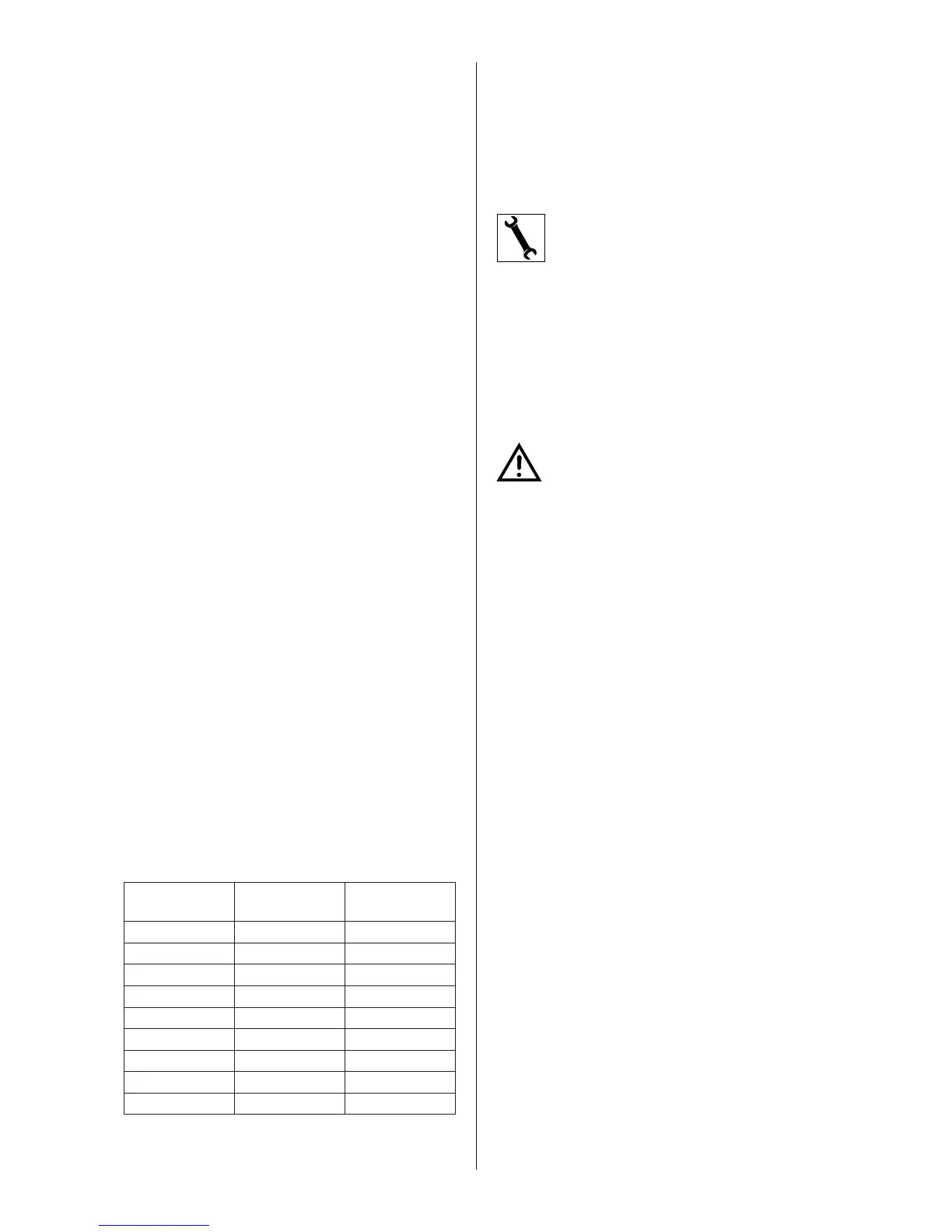
Push buttons A and B ÀDVK WR LQGLFDWH VHWWLQJ RI
heater pressure as follows:
LED PUSH
BUTTON A
LED PUSH
BUTTON B
PRESSURE
[bar]
ON ÀDVKHV 0,6
ON ÀDVKHV 0,7
ON ÀDVKHV 0,8
ON ÀDVK 0,9
ON ON 1,0
ÀDVK ON 1,1
ÀDVKHV ON 1,2
ÀDVKHV ON 1,3
ÀDVKHV ON 1,4
 Loading...