STILE_05.2022
STILE_05.2022
7
2
2
STILE
EN
STILE
EN
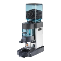
2 IDENTIFICATION OF THE APPLIANCE AND TECHNICAL DATA
2.1 Identifi cation of the parts of the doser grinder
1 Lid of the hopper
1
0
1
5
2
6
10
8
11
4
9
7
12
3
Fig. 1 - Identifi cation of the parts
2Coff ee bean hopper
3 Hopper shutter
4 Grinding degree adjustment ring
5 Grinding time display
6 Single Dose Button
7 Double Dose Button
8
Micro SW (active only in
"Preselection" mode)
9 Portafi lter button
10 Ground coff ee outlet
11 Fork for portafi lter
12 Main switch
2.2 Identifi cation of the appliance
An identifi cation label on the appliance bears the following data:
Manufacturer brand
Date of manufacture
Symbols and markings
Country of manufacture
Model
Voltage, Frequency, Duty cycle and Power
Manufacturer's address
Barcode
Serial number
2.3 Technical details
Doser grinder
STILE
Power supply (EUROPE market)
220-240V 50-60 Hz
Power supply (USA-CANADA market)
110-120V 60 Hz
Power [Watt@110-120V / Watt@220-240V] 249 / 190
Duty cycle @110-120V, 60Hz [ON / OFF ]
8 sec. / 200 sec.
Dimensions of appliance (L x W x H) [mm]
132 x 185 x 315
Net weight [kg]
5.5
Hopper capacity [kg] 0.3
Single dose grinding time [s] 6-7
Double dose grinding time [s] 11-12
Custom grinding time (manual) [s] 20
Grinding time tolerance [s] ± 0.1
Daily grinding [kg]
1-2
Single dose dispensing time recommended for 7g [s] 5
Double dose dispensing time recommended for 14g [s] 10
Noise [dB (A)] (with appliance in operation) 69
2.4 Safety devices of the doser grinder
All doser grinders RANCILIO GROUP S.p.A. are equipped with mechanical and
electromechanical devices designed to ensure the safety of the user and the
integrity/functionality of the appliance during its use.
In particular, the STILE doser grinder is equipped with the following safety devices:
• Motor thermal overload protection
The motor of the appliance has thermal overload protection which cuts out the power
supply to the motor itself in the event of overcurrent or overheating.
• Anti-intrusion button in coff ee loading hopper (Fig. 2)
The anti-intrusion button (detail 2) inside the feed hopper (detail 1) allows coff ee
beans to enter the grinding chamber while preventing the operator from accidentally
inserting his or her fi ngers.
• Coff ee loading hopper microswitch (Fig. 3)
A microswitch (detail 1), located inside the body of the appliance, allows the
appliance to be started only when the coff ee loading hopper (Fig. 2 detail 1) is in the
correct working position. Removing the hopper instantly deactivates the microswitch,
stopping the grinding motor.

 Loading...