B,
Coil ond
secure ony excess copillory
to
ovoid
pos-
ible domoge
due
to vibrotion.
Cofilbry coils Srould
be
no les
thon 2 inches in diometer
(3
incfres is reconr
mended). Silicone
odhesive opplied
between
lhe coib
will keep
them from rubbing.
9.
Although coiling ond
securing the
exces coprllay's
inr
portont
to dompen the effects of vibrotion. it
's
ir.rst
os
importont
to
ollow
enough slock in the
copillory so
thst
it is not iout
like
o "bonjo
string'.
10.
On
storiup of
the equipment.
obcerve
|tp
ccpncryfor
excessive
vibrotion
ond
moke
conecions os
:3
r -
rec
CONTROL
WIRING
l. Disconnect
eleciricol
power
to the
unit.
2. All Olectricolwiring
should conform
to the tJqtircrnl
Electricol Code ond
locol regulotions
3.
The electricol
rotings inside the control
cover
rnst
not be exceeded. See
below
for
DC rotirps
4. Use copper conductors
only.
5.
When
mounting o conduit
connectortolhe corF
trol frome,
toke core to not domoge the
contrd
mechonism
or the hinge
pin,
6.
The terminols
must not be bent cut off,
drilled
or
retopped.
Electricol leods
must not
be tout slock
must be ollowed
fortemperofure chonge
ond
vi-
brotion.
7. Attoch electricol leods to the switch terminols
us-
ing
the
screws
provided
(olso,
see below for the
Ol6),
tightened to l$20 inch
pounds,
*
The
furnished
cupwoshers
ore
to
be used on
the
O16 when
-
the conductor
wires
ore directly connected to the termircbl
The stripped
end
of
the
conductor should be mode
into
o
clockwise
formed
eye with on inside diometer to
siip over
the shonk
of
the
terminol screw. The
cup wosher,
with its
flonges outword,
should be
ploced
between the
ter"'mn';rct
ond the screw
heod to
copture
the
eye of the conc-:-:r
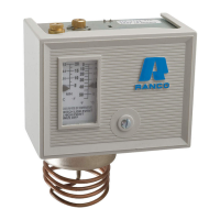
COTIIIROI SETTINGS
AND ADJUSTMENTS
AtICOI.ITROLSETTINGS ore
to
be osspecified bythe
equipment
imon'focturer ond
os
required for the opplicotion. DO
NOT
od-
tjust
the
pc*nters
beyond
the highest
ond
lowest morks on the
iscobolo+,e.
Ttre
scoleplote
is
only
for reference
ond
the finol
isettnqs
srroukl be
verified
with o
gouge
set. As o
finol
check,
ine
sf*,e.n
t'''ould
be run
through severol cycles
to
ossure
proper
I
settirps
qtd
irstollqtion.
;
LOWESI'
E\EM: DO
NOT set
the control below the lowest event,
:On
outonncrtb
reset controls,
if the
combinotion
of
the Ronge
;(R.H.
gc"'^'er)
minus
the
Differentiol
(1.H.
pointer)
is
lower thon
ifhe
1c.,.
,-
lvent,
the
control
will not
operote. See
Specifico-
tiors
ot'l
poge
4 for the Lowest Event.
fror,v
enrswmcoNTRoLs
ilow
pressti'e
co,ntrols
which ore used
to
cut-out
the
compressor
ion
preserre
drop sfrould
never
be set
fo
cut-out
(cut-in
minus
idiffere.*:^
l:
wer thon 2O
inches
of
vocuum
on
R I 2; single stoge
,1122
c: : -
s,stenns
should
never
be
set lower thon 3 inches of
vocuLrn.
Excessively
low
settings con
couse compresor dom-
oge.
Manrol
reset
Ol6 bw
presure
controls
hqve.o scobplote thot
indcotes
tfre
pressure
of
which
switch
terminols 2-3 will
lock
open
on
pressure
drop
(DO
NOT set
the
pointer
below
the Lowest
F
Event) The
pressure
must
rise
opproximotely
l0
PSIG
obove this
I
setir'
;
before the
control
con be
reset.
-
HIGH PRESSURE
CONIROIS
High
pressure
contro,ls
whbh
ore used
to
cut-otrt
the
compres-
..
sor
on
pressrrre
rbe
sfroukJ
norrnolty
be set not higher
thon the
volues shown below:
Refrigeront
Cut-outSettings
Type
Air Cooled Woter Cooled
Rlz
230
psi
230
psi
R22 360osi 3ffiosi
R5@
380psi 300psi
rSorne
high
presqJre
controls ore equipped with limit stops. Al-
thor.rgh the
control setting con be odjusted,
the limit
stop
pre-
venls
odjusfment
higher thon the limit
stop
foctory
setting. DO
NOT force the
odjuslrnent beyond
the limit
stop
setting.
l
iMonuot
reset
Ol6
high
pressure
controls hove o scoleplote thot
gindlcotes
the
press.rre
ot
whbh
svitch
terminols
2-l
will lock
open
ion
pressr.rre
rbe. the
pressJe
must drop opproximotely 40 PSIG
,below
thb
selling before
the
control con be
reset.
-,--'
i
rri
.i{
-+
+a
DC
RAilNGS
GorAGrrtdccscrl
\btts FTA ln^ Nl
IPDVA
Ol0 ond Ol
I
wirh
r397qu-2
mognet
pockoge
instolled
32
9.3 93
72
7.3 73
lt5 4.6 46
575
230 2.3 23
575
o20
I'AJ 4.6 46 3 )/
240 2.3 23
0.5 575
Cfi] b/.5
,t,€
 Loading...