P033458
2
3
4
1
P3
P2
P1
P4
5
6
P6
P5
P028728
6
P6
5 P5
4
P4
7 P7
8 P8
2
P2
1 P1
3 P3
P033458
2
3
4
1
P3
P2
P1
P4
g/y
b
w
bk r
v
br
r
or
or
bk
y
v
w
b
g/y
bk
br
gr
br
or
br
bk
v
br
wb
bk
w
br
br
br
brb
v
r
y
gy
w r
bk
v
r
bk
b
v
v
br
br
bk
br
r
r
r
bk
b
bk
b
b
b
b
b
b
b
b
b
b
b
w
gr
y
r
or
or
b
w
bbb w
b
or
br
v
b
b
b
b
b
b
b bw
b
w
w
w
r
v
v
b
r
v
br
br
gr
y
b
v
v
br
br
bk
bk
E
A2
C
A1
B1
A3
B3
B4
B2
B5
B6
B7
D2
I
D1
D3
B8
D4
F
G1
I
H
I
H
G2
I
H
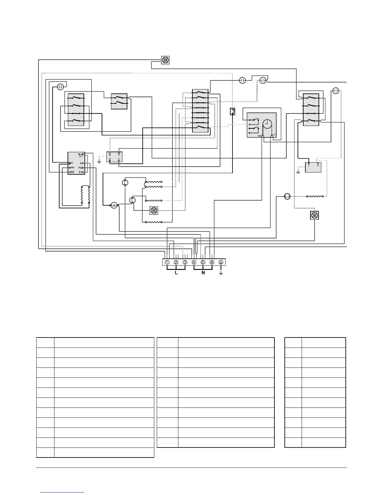
Code Description
A1 Grill front switch
A2 Grill energy regulator
A3 Grill elements
B1 Left - hand oven front switch
B2 Left - hand oven thermostat
B3 Left - hand oven top element (outer)
B4 Left - hand oven top element (inner)
B5 Left - hand oven centre element
B6 Left - hand oven fan
B7 Left - hand oven base element
B8 Left - hand multi - function switch
Code Description
C Clock
D1 Right - hand oven front switch
D2 Right - hand oven thermostat
D3 Right - hand oven element
D4 Right - hand oven fan
F Cooling fan
G1 Light switch
G2 Oven light
H Thermal cut - out
I Neon
Circuit Diagram: Multi-function Oven (Classic Deluxe)
Code Colour
b Blue
br Brown
bk Black
or Orange
r Red
v Violet
w White
y Yellow
g/y Green/yellow
bk/w Black/white