Do you have a question about the Ranger Communications RCI-2950 DX and is the answer not in the manual?
| Frequency Range | 28.000 - 29.700 MHz |
|---|---|
| Input Voltage | 13.8 V DC |
| Antenna Impedance | 50 Ohms |
| Power Supply | 13.8V DC |
| Mode | AM/FM/SSB |
| Receiver Sensitivity | 0.5 µV |
| Channels | 40 |
Details general specifications like model, frequency range, tuning steps, emission modes, and input voltage.
Lists transmitter specifications including RF power output, transmit modes, modulation, and antenna impedance.
Covers receiver specifications such as sensitivity, image rejection, AGC, and audio output power.
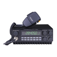
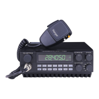
Provides a general overview of the RCI-2950 DX / RCI-2970 DX dual band mobile transceiver.
Lists key features of the RCI-2950 DX / RCI-2970 DX transceiver, such as power output and mode operation.
Explains basic operating procedures for the RCI-2950 DX / RCI-2970 DX transceiver.
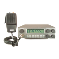
Details front panel controls (Frequency Selector, RF Power, Mic Gain, Volume, Squelch, RF Gain, Clarifier, Mode) and rear panel connections (Antenna, CW Key, Ext. SP, PA SP, Power).
Describes the microphone's PTT switch and remote up/down controls for frequency adjustment.
Covers channel selection, mode selection, RF power control, receive scanning, split function, memory functions, and basic receive/transmit procedures.
Explains basic programming procedures for the RCI-2950 DX / RCI-2970 DX transceiver.
Details three methods for selecting operating frequencies using front panel controls, microphone buttons, or the frequency select knob.
Covers methods for frequency scanning, including scanning all frequencies between set limits and scanning programmed memory channels.
Explains how to use the split frequency feature for FM repeater operation, allowing offset transmit frequencies.
Explains the technical theory of operation for the RCI-2950 DX / RCI-2970 DX mobile transceiver.
Describes the Phase Lock Loop circuit's role in generating local oscillator and exciter signals for receive and transmit operations.
Details the receiver's signal path from antenna to audio output, including pre-amp, mixer, filter, and detection stages.
Explains how audio signals modulate RF signals in AM, FM, and SSB modes, including amplification stages.
Describes the process of amplifying the exciter signal through various amplifier stages before transmission.
Lists essential test equipment required for transceiver alignment and setup.
Details PLL, Transmitter (TX Power, APC, BIAS Current, RF Power, ALC, CW TX, AM/FM Modulation), and Receiver alignment steps.
Lists precautions to prevent damage to the transceiver during use and alignment.
Outlines key items for regular inspection to ensure continued performance, such as antenna and cable checks.
Provides guidance on fuse replacement, including the correct rating and the importance of finding the cause of a blown fuse.
States that electrical and mechanical parts information is included in the parts list, with reference designators in alphanumeric order.
Provides contact information for ordering replacement parts from the manufacturer's parts department.