Rans Inc. Section 8
Model S-7LS COURIER Required Placards and Markings
REVISION - A May 8, 2007 8- 2
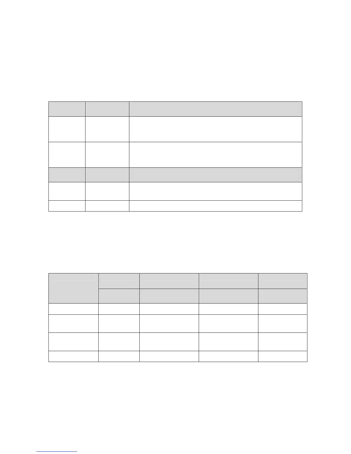
AIRSPEED INDICATOR MARKINGS
Airspeed indicator markings and their color code meanings are shown in Table 8-1.
Marking IAS Value or
Range(mph)
Meaning
White Arc 45 - 69 Full Flap Operating Range. Lower limit is maximum weight
stalling speed in landing configuration. Upper limit is
maximum speed permissible with flaps extended.
Green Arc 50 - 97 Normal Operating Range. Lower limit is maximum weight
VS at most forward CG with flaps retracted. Upper limit is
maximum structural cruising speed.
Marking IAS Value or
Range(mph)
Meaning
Yellow Arc 97 - 128 Operation must be conducted with caution and in smooth
air only.
Red Line 128 Maximum speed for all operations
Table 8-1: Airspeed Indicator Markings
POWER PLANT INSTRUMENT MARKINGS
Power plant instrument markings and their color code meanings are shown in Table 8-2.
Red Line Green Arc Yellow Arc Red Line Instrument
Minimum
Limit
Normal
Operating
Caution Area Maximum
Limit
Tachometer 1400 – 5500 RPM 5500 – 5800 RPM 5800 RPM
Cylinder Head
Temperature
275 ° F
Oil
Temperature
120° F 190° –230° F 230° - 266° F 266°
Oil Pressure 12 PSI 29 – 73 PSI 100 PSI
Table 8-2: Power plant instrument Markings
 Loading...