Hopper Cover Assembly
MDS
5900041-b-de/en/fr-0199 6 R.K..
Basically, hopper cover assemblies on all spreaders are the same. However,in
most cases holes must be drilled in the hopper or extension sets for the „lever
mechanism“ before the hopper cover can be attached. In the following table,
the left-hand column specifies the basic machine with its corresponding exten-
sion set possibilities. The right-hand column specifies the corresponding dia-
gram which gives the particular dimensions and hole pattern for that specific
spreader model and ist extension kit is fitted.
Basic model (+ Hopper extension) Diagram
ALPHA / MDS 1121
1
(+B 253) 2
(+B 310) 1
(+B 413) 2
(+B 610) 1
(+B 910) 1
BETA / PK 1100
1
(+B 253) 2
(+B 310) 1
(+B 413) 2
(+B 610) 1
(+B 713) 2
(+B 910) 2
DELTA / PK 1500
1
(+ 1600) 1
(+ 1750) 2
(+ 2000) 1
(+ 2500) 1
MDS 701 / 721 / 732 / 901 / 921 / 932
1
ZSB
1
• Select hole pattern according to Dia.1 or Dia.2 depending on model.
• Drill holes for the round studs in the hopper or hopperextensions ( see cor-
responding Diagrams 3,4,5).
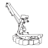
• Bolt on round studs (Dia. 3,4,5 - Fig.1) using bolts (Dia. 3,4,5 - fig.2) was-
hers and nuts (Dia. 3,4,5, - Fig. 3 and 4).
Attention: With spreaders fitted with the 3-sided hopper extension,
the preassembled rod (Dia.6, Fig.5) of the hopper cover AP 9 / AP 10
must be pulled out. The feed the hopper cover extensions APE 9 /
APE 10 into the hopper cover and replace the rod (Dia.6, Fig.5).
 Loading...