20 0700-M010-0 RAV4300 A3
3.3 Ponti con sollevatore integrato (RAV4351SI, 4352SI,
4355SI, 4356SI, 4401SI, 4402SI, 4405SI, 4406SI)
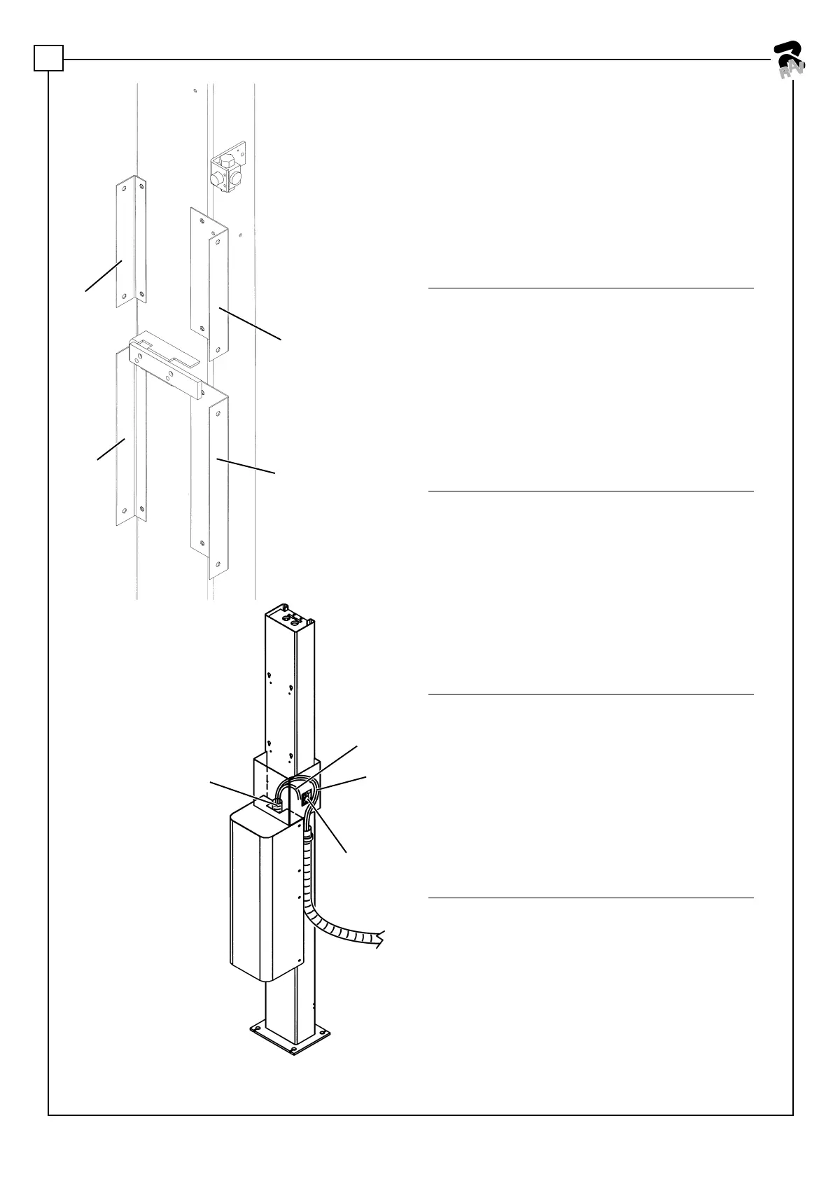
A Smontare l'intera centralina dal supporto che la collega
alla colonna comando 34 (Fig.2).
B smontare il serbatoio 36 e rimontarlo ruotato di 90°
posizionando il tappo 35 sotto alle elettrovalvole di
comando.
C eseguire sulla colonna comando una serie di fori
secondo le indicazioni riportate in Figura 5 in funzione
del modello di ponte in possesso.
D fissare gli angolari 5, 6, 19, 20 sulla colonna comando
come indicato in Fig. 9 utilizzando le viti in dotazione;
E montare la piastra di interfaccia 2 o 3 o 4 come indicato
in Figura 2 utilizzando le viti 14 ed impegnando i fori
3.3 Lifts with lift table (RAV4351SI, 4352SI, 4355SI,
4356SI, 4401SI, 4402SI, 4405SI, 4406SI)
A Disassemble the whole control unit from the support
connecting it to the control column 34 (Fig.2).
B Disassemble the tank 36 and assemble it again with a
90° rotation after placing the plug 35 under the control
solenoid valves.
C Drill a series of holes on the control column according
to the instructions in fig. 5 depending on the lift model
you have.
D Mount the angle bars 5, 6, 19, 20 on the control column
as reported in fig. 9 by using the dedicated screws;
E mount the interface plate 2 or 3 or 4 as reported in fig.
3.3 Hebebühnen mit integriertem Heber (RAV4351SI,
4352SI, 4355SI, 4356SI, 4401SI, 4402SI, 4405SI,
4406SI)
A Die gesamte Zentrale vom Halter nehmen, der sie mit
der Steuersäule 34 (Abb.2) verbindet.
B Den Behälter 36 abnehmen und nach einem Drehen
um 90° montieren, dabei den Verschluss 35 unter den
Steuerventilen ausrichten.
C An der Steuersäule nun, den Angaben der Abbildung
5 gemäß und in Abhängigkeit zum entsprechenden
Hebebühnenmodell, die erforderliche Anzahl an
Bohrungen setzen.
D Die Winkelstücke 5, 6, 19, 20, den Abgaben auf der
3.3 Ponts avec élévateur intégré (RAV4351SI, 4352SI,
4355SI, 4356SI, 4401SI, 4402SI, 4405SI, 4406SI)
A Démonter toute la centrale du support qui la relie à la
colonne de commande 34.
B Démonter le réservoir 36 et le remonter tourné à 90° en
positionnant le bouchon 35 sous les électrovannes de
commande.
C Sur la colonne de commande, réaliser une série
d’orifices selon les indications de la Figure 5 en fonction
du modèle de pont en votre possession.
D Fixer les cornières 5, 6, 19, 20 sur la colonne de
commande comme indiqué Fig. 9 en utilisant les vis en
dotation.
3.3 Puentes con elevador integrado (RAV4351SI,
4352SI, 4355SI, 4356SI, 4401SI, 4402SI, 4405SI,
4406SI)
A Desmontar toda la central del soporte que la conecta a
la columna de mandos 34.
B Desmontar el depósito 36 y volverlo a montar girado a
90°, colocando el tapón 35 debajo de las electroválvulas
de mando.
C Efectuar una serie de agujeros sobre la columna de
mandos, siguiendo las instrucciones ilustradas en la
Figura 5, en función del modelo de puente que uno
posee.
D Fijar los angulares 5, 6, 19, 20 sobre la columna de
mandos como se indica en la Fig. 9, utilizando los
Fig. 9
3
29
18
27-28
40
5
19
6
20
 Loading...