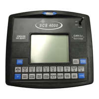
Do you have a question about the Raven SCS 4600 and is the answer not in the manual?
Channels | 4 |
---|---|
Inputs | 4 XLR/TRS combo |
Outputs | 2 XLR, RCA |
EQ Bands | 3-band |
Phantom Power | Yes |
USB Interface | Yes |
How to enter and use Edit mode for programming numerical values into the SCS console.
Lists abbreviations and their corresponding definitions for units of measure.
Explains how to convert meter CAL values and lists conversion factors.
General safety guidelines, including warnings and procedures for safe operation.
Safety precautions related to working with hydraulic systems connected to the console.
Safety guidelines for electrical connections, polarity, and maintenance.
Explains how SCS systems simplify and improve product coverage uniformity.
Describes the various components that make up the SCS control systems.
Details the display area and keypad of the SCS console for user interface.
Describes the features of the SCS 4000/5000 consoles, including manual flow control.
Details the features of the SCS 4070 console, including boom section control.
Explains the features of SCS 4400/4600 consoles, including data logging.
Provides guidelines for proper care and use of the SCS console, including mounting.
Lists the technical specifications for the SCS console, including dimensions and environmental ratings.
Information on obtaining manual and software updates for Raven consoles.
Procedure for the SCS console to communicate with and detect connected CAN nodes.
Displays program and version information for each detected node on the CANbus.
Steps to reinitialize the CANbus system if nodes are not detected.
Process to reconfigure product control node order on the CANbus.
Instructions on how to program CAN nodes using the SCS console in Edit mode.
General troubleshooting techniques for CAN systems, similar to hard-wired systems.
Lists common causes for loss of CAN communication between the console and nodes.
Requirements for selecting a mounting location for the SCS console inside the machine cabin.
Steps for mounting the SCS console using provided hardware and clamps.
Instructions for connecting the console cable and routing power to the SCS console.
Procedure to reset the SCS console's internal memory to initial programming screens.
Steps for the initial calibration, starting with adjusting contrast and setting language.
Setting the measurement units (US Acres, Hectares, etc.) for the console.
Selecting the type of product control (Liquid, Granular, Spinner, NH3).
Selecting the type of control valve used with the SCS console.
Inputting the spreader constant for granular applications.
Inputting the product density for granular applications.
Inputting the meter calibration value for liquid product applications.
Inputting fan speed calibration for spinner applications.
Programming the valve calibration number to adjust control valve response.
Entering the target application rate for product application.
Selecting the type of speed sensor used by the console.
Recommends initial speed calibration values and procedures for refining them.
Programming boom section widths for accurate application.
How to change initial console programming settings after setup.
Overview of programming the SCS console using calibration keys.
Detailed explanation of how to enter and use Edit mode for programming.
How calibration keys are used to program and calibrate the system.
Specific instructions for accessing and entering boom widths.
Instructions for accessing speed calibration.
Instructions for accessing meter calibration for different product types.
Detailed explanation of valve calibration and its parameters.
Explanation of the rate calibration function.
How to use the self-test mode for checking the product control system.
Explains the use of function keys for displaying application information.
Displays current volume per minute or flow rate.
Estimates area coverage based on current speed and boom operation.
Accesses the SCS Data Menu for further settings.
Toggles product control on or off.
Displays current volume remaining in the tank or bin.
Toggles product selection on the controller.
Simulates speed for testing the system without the vehicle moving.
Feature to increase system accuracy at low application rates.
Contains options related to serial communication and data logging.
Enables or disables data logging and specifies conditions for its use.
Allows entry of a reference number to represent a job.
Sets the baud rate for communication with a GPS receiver.
Selects baud rate for serial port communication.
Enables or disables alarms for variable rate changes.
Determines how often data is sent to the serial port.
Selects units for data logging trigger values.
Options for serial communication and data direction.
Contains options for product settings and assignments.
Assigns products to individual boom sections for application.
Sets acceptable percentage deviation for application rate and triggers alarms.
Sets the maximum desired RPM or hydraulic output for PWM control valves.
Sets the minimum desired RPM or hydraulic output for PWM control valves.
Sets the coil frequency for PWM valves.
Sets initial pulse width for PWM valves in PWM-Close mode.
Sets target pressure for liquid systems in standby condition.
Sets increment for rate adjustments using INC/DEC switch.
Controls valve to low flow limit and activates alarm if volume/minute falls below assigned limit.
Activates low level alarm when tank volume falls below a defined level.
Sets delay between console controlling flow rate and booms being turned on.
Sets the spreader constant for granular applications.
Fine-tunes control valve response for PWM mode applications.
Sets pulses per revolution for pump/fan RPM readout.
Sets tolerance for flow switch and dual encoder readings to trigger alarms.
Enables or disables vacuum or bin level alarms for chemical injection or granular applications.
Enables or disables flow switch alarms for chemical injection.
Sets time for valve to open when booms are turned off in automatic mode.
Displays current PSI, kPa, or BAR pressure readings.
Calibrates pressure transducer #1.
Calibrates pressure transducer #2.
Enables or disables a chemical agitator.
Indicates PWM valve position for fine-tuning offsets.
Enables standby pressure setting for PWM valves.
Sets minimum pressure for liquid product systems to maintain control.
Feature for low application rates using flow meter and pressure transducer.
Automatically calibrates high and low offset values for PWM control valves.
Enables quicker control responses for granular applications by predicting PWM valve duty cycle.
Contains options for console display and settings.
Adjusts screen contrast for readability.
Toggles audible alarms on or off.
Smooths rate display during product applications.
Sets the current date and time.
Sets delay before console enters low power mode and loses time settings.
Prohibits calibration value entry without a data lock code.
Displays console software program and revision level.
Enables or disables ratio rate application mode for multiple products.
Shuts off product control if speed drops below a set limit in automatic mode.
Options for checking CAN communication and node status.
Indicates status of boom sense/speed node.
Toggles speed signal source for SCS 4070.
Indicates status of AutoBoom control node.
Indicates status of a row sense node.
Reconfigures product control node order.
Indicates status of AccuBoom control node.
Reviews current values and settings for configured product channels.
Describes data logging system and setup for SCS 4400/4600 consoles.
Steps to set up the data logging system with a compact flash card.
Descriptions of visual and audible alarms for the SCS console.
Recommends initial speed calibration values and procedures for refining them.
Detailed procedure for calibrating wheel drive speed sensors.
Adjusting speed calibration for systems with additional wheel magnets.
Procedure for calibrating speedometer drive speed sensors.
Procedures related to liquid sprayers.
Calculating and programming boom section widths for liquid sprayers.
Formula for calculating adjusted applied rate in band spraying.
Finding and copying flow meter calibration numbers.
Programming valve calibration numbers for control valve response.
Controls time of first correction pulse after direction change.
Controls response time of the control valve motor.
Sets percentage from target rate for slower turn to avoid overshoot.
Allowable difference between target and actual application rate.
Programming target application rate and checking gate opening capability.
Setting up spinner RPM control and associated calibration values.
Programming data through VOLUME/TANK key.
Entering estimated volume of product in tank or bin.
Setting up an alarm for low tank volume.
Resetting display values like Total Area, Total Volume, etc.
Sets max volume per minute before tiers 1 and 2 are enabled in 3-tier systems.
Percentage factor to disable higher tier based on volume settings.
Settings for dual loop control feature for low application rates.
Sets system response to rate control inputs based on flow meter data.
Adjusts system aggressiveness and response to pressure changes.
Procedures for granular application systems.
Entering boom widths for granular applications.
Calculating and verifying the spreader constant for granular applications.
Formula to calculate spreader constant for metric rate display.
Procedure to verify and refine the spreader constant.
Entering product density for spreader constant calculation.
Setup and testing procedures for liquid applications.
Steps for initial job setup, including filling tank and verifying settings.
Procedures for testing the console's speed display and rate correction.
Regular maintenance procedures to ensure system longevity.
Setup and testing procedures for granular applications.
Steps for initial job setup for granular applications.
Information on speed sensor extension cables and connectors.
Steps to test the speed sensor cable for proper voltage and signal.
Information on flow meter/encoder extension cables and connectors.
Steps to test the flow meter cable for proper function.
Specifies firmware versions needed for console-to-console communication.
Recommended guidelines for operating multiple consoles on a CANbus.
Procedures for setting up Viper Pro and Envizio Pro consoles for CAN product control.
Steps to set up the Viper Pro console for CAN product control.
Steps to set up Envizio Pro consoles for CAN product control.
Step-by-step guide to recalibrate the flow meter for accurate readings.
Diagram and notes for handgun installation with the ratio rate feature.
Steps for operating a handgun in conjunction with the ratio rate feature.
Instructions for using a USB to Serial adapter for console updates.
Steps to prepare the computer and adapter for firmware updates.
Guide to using the serial console updater utility for firmware updates.
Instructions for using HyperTerminal for firmware updates.
Commands and strings for remote computer control of the SCS console.
Format for requesting rate changes from a remote computer.
Output strings from the SCS console to a remote computer.
Output strings from SCS 4400/4600 consoles to a remote computer.