Wuhan Raycus Fiber Laser Technologies CO., Ltd.
Pulsed Fiber Laser User’s Guide V2.1
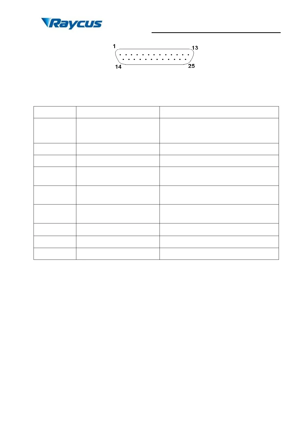
Figure 5. Connect port of controller
Table 3Definition of connect ports of controller
8 bit Parallel port;
D0 is minimum bit and D7 is maximum bit;
Range: 0-255 (hexadecimal: 0X00-0XFF); 0 is
minimum power and 255 is maximum power.
see alarm codes in the table below
+5V DC power supply input,
providing power for inside chips of DB25 to ensure
that the input and output signals are valid.
Emission Enable (EE) signal.
HIGH: Emission Enable
LOW or disconnected: Emission Disable
Emission Modulation (EM) input.
HIGH (>3V): Emission ON
LOW or disconnected (<1V): Emission OFF
Pulse Repetition Rate (Synchronization) input,
square wave.
Guide Laser (red diode) ON/OFF input.
a) The pump current of diode laser and the laser output power are controlled by setting
the value of PIN1-PIN8 (TTL level). PIN1-PIN8 can be set from 0 ~ 255,
corresponding to the laser output power from 0~100% (the actual laser power may
not be strictly linear with the setting value). The relationship between PIN value and
output power is shown in Table 4:
b) PIN 10,13,14,15,24,25 are all digital GND.
c) PIN 17 is the external 5V DC input, providing power for inside chips of alarm signal to
ensure that alarm signals are valid.
d) PIN 18 is the start signal of the MO. PIN19 is the input for the optical output signal.
The electrical level for both PIN18 and PIN19 are 5V. Before turning on PIN 19, MO
signal must be switched ON, in other word, the signal of PIN 18 must be ahead of PIN