Wuhan Raycus Fiber Laser Technologies CO., Ltd.
Pulsed Fiber Laser User’s Guide V2.1
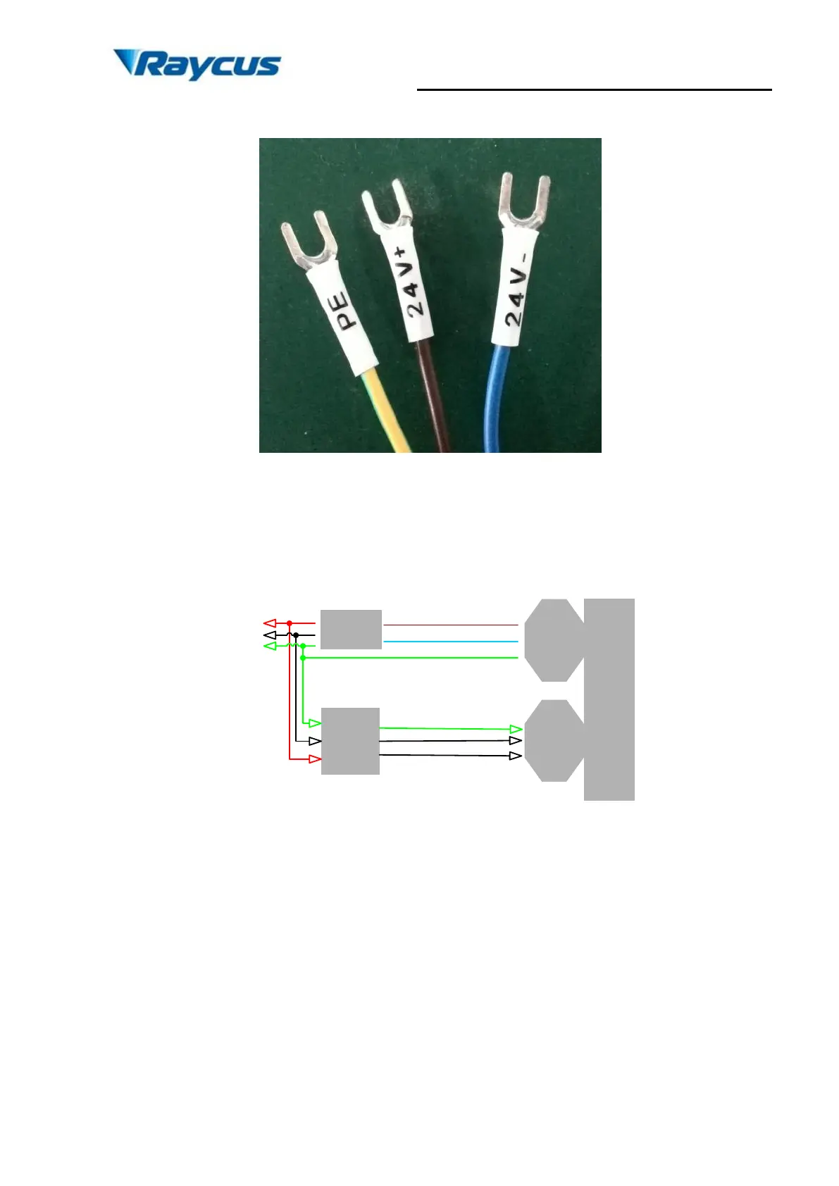
green. The definition figure is shown in Fig. 3.
Figure 3. Definition of power line wires
c) Make sure that the interface of the external controllermatches the laser and the control
cable is well connected to the laser’s interface. The recommended electrical connection
is shown in Fig. 4.
User’s
controller
DB25
Controller
interface
Power
supply
wire
Laser
Module
24V+(Brown)
L
N
GND
External GND
24V
power
supply
24V-(Blue)
Figure 4. Schematic of recommended electrical connection
d) The bending radius of the delivery fiber should not exceed 15cm.
3. Control Interface
There are DB9 and DB25 interfaces at the rear of the laser. The DB9 is a RS232 interface
only used for debugging, no needs to connect. And DB25 is the joint interface connecting control
system with laser system, please make sure the connection is reliable before operation. Feet of
the DB25 are defined as follows in Fig. 5.