User’s guide Ytterbium Pulsed Fiber Laser RFL-P70Q~P100Q Ver.: 2.0
6 / 9
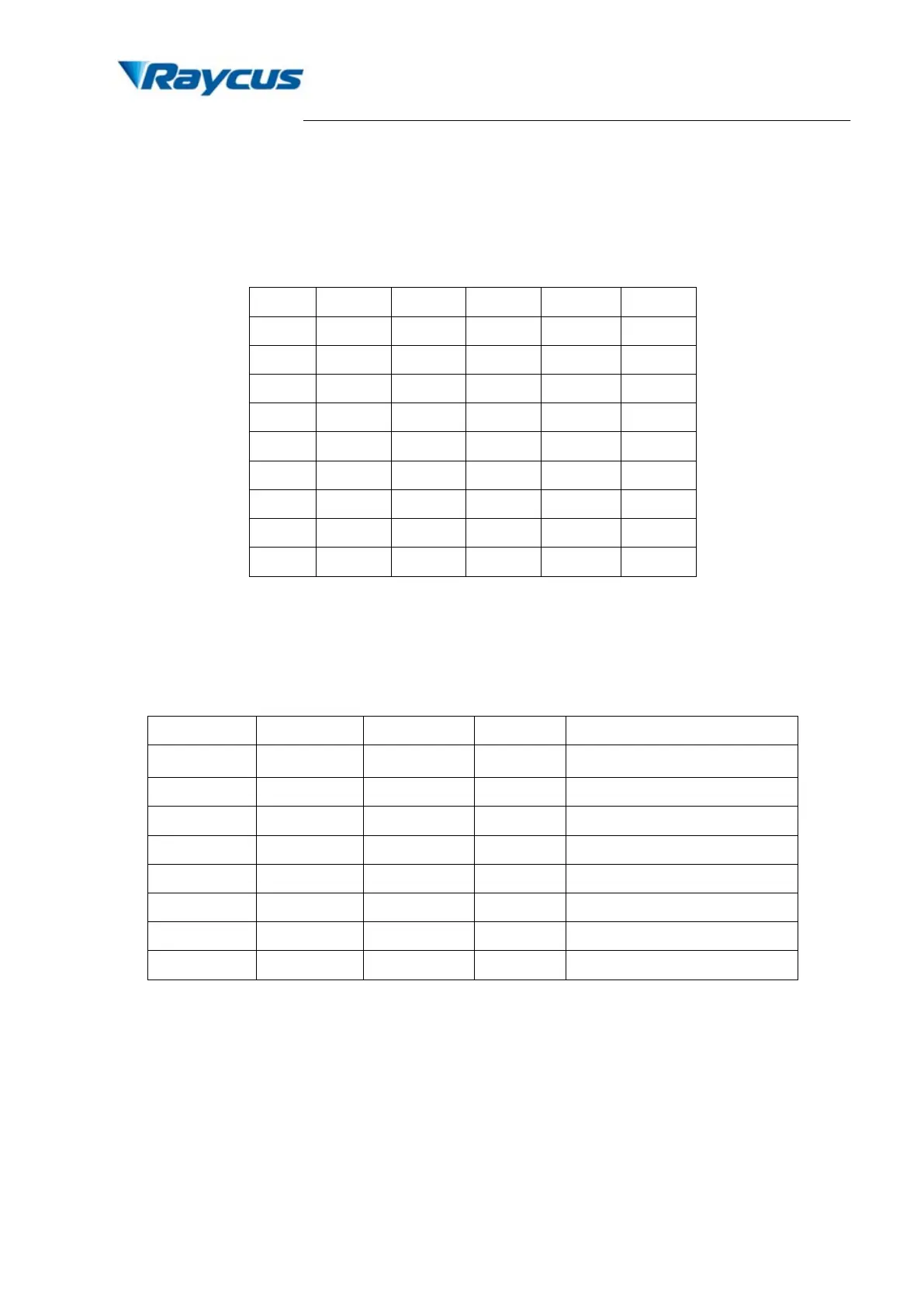
laser output power from 0~100% (the actual laser power may not be strictly linear with the
setting value). The relationship between PIN value and output power is shown in Table 4:
Table 4 Definition of power control PIN value
PIN 2 0 0 0 0 1
PIN 7 0 1 1 1 1
2) Alarms status: Pins 11, 12, 16 and 21 are the alarm and status outputs. Pin 12 is reserved
(always be high). These pins indicate the following device states.
Table 5 Definition of alarm signal
×
Low Low Low Temperature alarm
×
×
×
×
×
High Low High Obligate alarm
×
×
3) PIN 17 is the external 5V input, providing power supply for alarm signal; input current must
be > 20 mA.
4) External input signals (PIN 1-8, 18-20, 22) are all connected to the optical coupler inside the
system. External 17 pin 5V power supply should be connected to ensure the effective signal.
Caution: Before turning on PIN 19, PIN 18 must be switched on, or the laser may be
damaged. The signal of PIN 18 must be ahead of PIN 19 at least 5 ms.
 Loading...