-_.
-
.
_. .
.___-
----
.-.__
x..
--.
-
..-_._.
_-.
_-..
-..
.
--..
.
..------.--...-.---.--.
.-
.-..
.-
.
.
.
_
-.
.
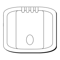
SLOPING RUDDERSTOCK
I
PORTHAND MOUNTING
In
certain circumstances
il
may be more
convenient to mount
Ihe
unit on the
porthand
side. When
lhis
is Ihe case, Ihe
changeover
switch
will require
adjslmenl as
lollows.
Remove the
blanking screw and use Ihe adjusler
provided lo rolale Ihe
swilch
anli-
clockwise
unlil
the
endslop is reached
(Fig. 2.)
Never force the changeover
rwllch,
light
pnraure only
Is
required.
Finally replace and
lully
lighlen Ihe
blanking screw lo ensure walertighlness.
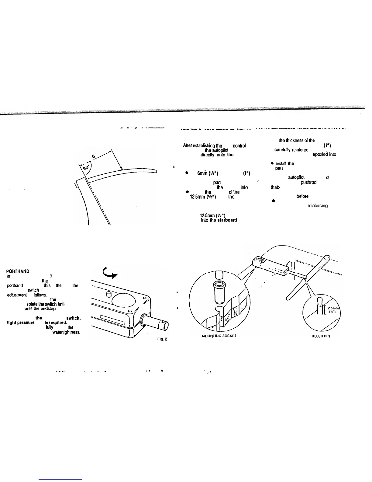
BASIC INSTALLATION
Aller eslablishing Ihe lhree conlrol
dimensions Ihe aulopilot can be
mounled direclly onlo the Slarboard
cockpil seal (Fig. 3). Proceed as lollows.
I
TILLER PIN (Cal No. 0001)
0
Drill
6mm
(Y4”) hole x 25mm
(1”)
deep
al poinl marked.
I
l
Using a Iwo part epoxy such as
*
Araldile, epoxy Ihe liller pin
inlo
place;
0
Posilion Ihe shoulder
01
Ihe pin
12.5mm (Vz”) above Ihe liller surlace.
MOUNTING SOCKET
(Cal No. 0002)
l
Drill
125mm
((/2”)
hole x 25mm (t”)
deep inlo Ihe etarboard cockpil seal.
l
II Ihe lhickness
01
Ihe mounling
posilion is less lhan 25mm (1”)
carelutly reinlorce the under surlace
with a plywood plate epoxied
inlo
posilion;
0
lnslall
the mounling socket using two
par1
epoxy;
Note The aulopilol is capable
01
generaling high pushrod loads. Ensure
Ihat:-
l
The epoxy is allowed lo harden
Ihoroughly belore applying any loads;
0
All holes are drilled lo correct size and
where necessary reinlorcing is
provided.
Fig. 3
2
. .
._..
.
.
.
-
._
a
3
 Loading...