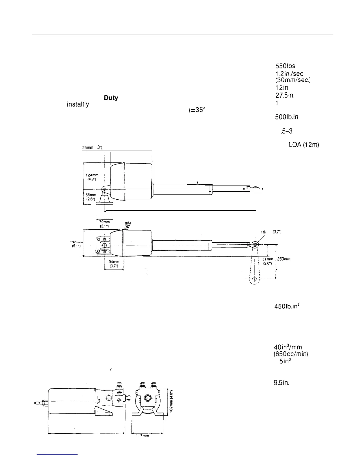
1.2.2 LINEAR DRIVE UNIT
The output ram of the linear drive unit is driven
by a declutchable re-circulating ball leadscrew
which enables the drive unit to .be permanently
coupled to the rudder stock via a simple crank
or tiller arm. The drive is automatically engaged
by means of an internal friction clutch when the
autopilot is switched to Duty and will
disengage instaltly even under heavy load
when the autopilot is switched to Set or Off.
25mm
(1
.o”) 207mm (6.15”)
Supply voltage
Peak thrust
Maximum stroke speed
Maximum stroke
Overall length at mid stroke
Tiller arm length
(+35” rudder)
Maximum rudder torque
Power consumption (typical
average)
Suitable for vessels up to
12 volts
550lbs (225Kg)
1.2in./sec.
(30mm/sec.)
12in.
(300mm)
27.5in.
(700mm)
1
Oin. (260mm)
500lb.in.
(570Nm)
1
Z-3
amps
40ft.
LOA
(12m)
51 mm (2.0”)
_
,-
_
JJ
1
,
/
! 1
700mm lZ7.5”)
I
I
mm (0.7”) RADIUS
260mm
(10.0”)
--+j$--
r
1.2.3 HYDRAULIC DRIVE UNIT
The hydraulic drive unit consists of a precision
gear pump with integral valve block driven by a
continuously rated servo motor. A special
pressure balance valve corrects the effects of
hydraulic slip and isolates the pump from the
steering circuit when the autopilot is not
energised.
,
Supply voltage
Regulated peak pressure
Flow control
Peak flow rate (unloaded)
Maximum ram capacity
Power consumption (typical
average)
Overall length
12 volts
4501b.in2
(30 bar)
integral pilot
check and
pressure
balance valve
sys tern
40in3/mm
(650cc/min)
1 5in3 (25Occ)
2-3.5 amps
9.5in.
(240mm)
/L/
240mm (9.5”) 117mm (4.6”)
 Loading...